Heat dissipation apparatus

a heat dissipation apparatus and heat dissipation technology, which is applied in lighting and heating apparatus, indirect heat exchangers, and semiconductor/solid-state device details. it can solve the problems of heat dissipation efficiency reduction, heat dissipation apparatus dissipation heat, and electrical components may overheat, so as to promote heat dissipation and dissipate heat. , the effect of dissipation

Inactive Publication Date: 2007-08-23
HON HAI PRECISION IND CO LTD
View PDF11 Cites 24 Cited by
  • Summary
  • Abstract
  • Description
  • Claims
  • Application Information

AI Technical Summary

Benefits of technology

[0006]The present invention relates to a heat dissipation apparatus for dissipating heat generated by a heat generating electronic component. According to a preferred embodiment of the present invention, the heat dissipation apparatus includes at least one heat pipe, a fin assembly, a centrifugal blower for promoting heat dissipation in the fin assembly, and an enclosure made of thermally conductive material. The heat pipe has an evaporating section thermally connecting with the heat generating electronic component, and first and second condensing sections respectively connecting with the enclosure and the fin assembly. The enclosure absorbs and helps to dissipate the heat generated by the heat generating electronic component. The heat dissipation surface area is thus increased and as a result the heat dissipation efficiency of the heat dissipation apparatus is improved. Furthermore, since the heat dissipation apparatus is directly secured to the enclosure, weight of the heat dissipation apparatus and accordingly weight of a computer including the heat dissipation apparatus can be reduced. Moreover, a vibration and noise produced by operation of the heat dissipation apparatus can be lowered.

Problems solved by technology

If the heat is not timely removed, these electronic components may overheat.
However, the heat dissipation apparatus dissipates the heat only by making use of the fin assembly.
Thus, the heat dissipation surface area is relatively small and the heat dissipation efficiency of the heat dissipation apparatus is accordingly reduced.
Furthermore, the conventional heat dissipation apparatus increases the weight of the computer, and generates vibration and noise during operation thereof since it is a separate module from the enclosure of the computer.

Method used


Image

  • Heat dissipation apparatus
  • Heat dissipation apparatus
  • Heat dissipation apparatus

Examples


Embodiment Construction

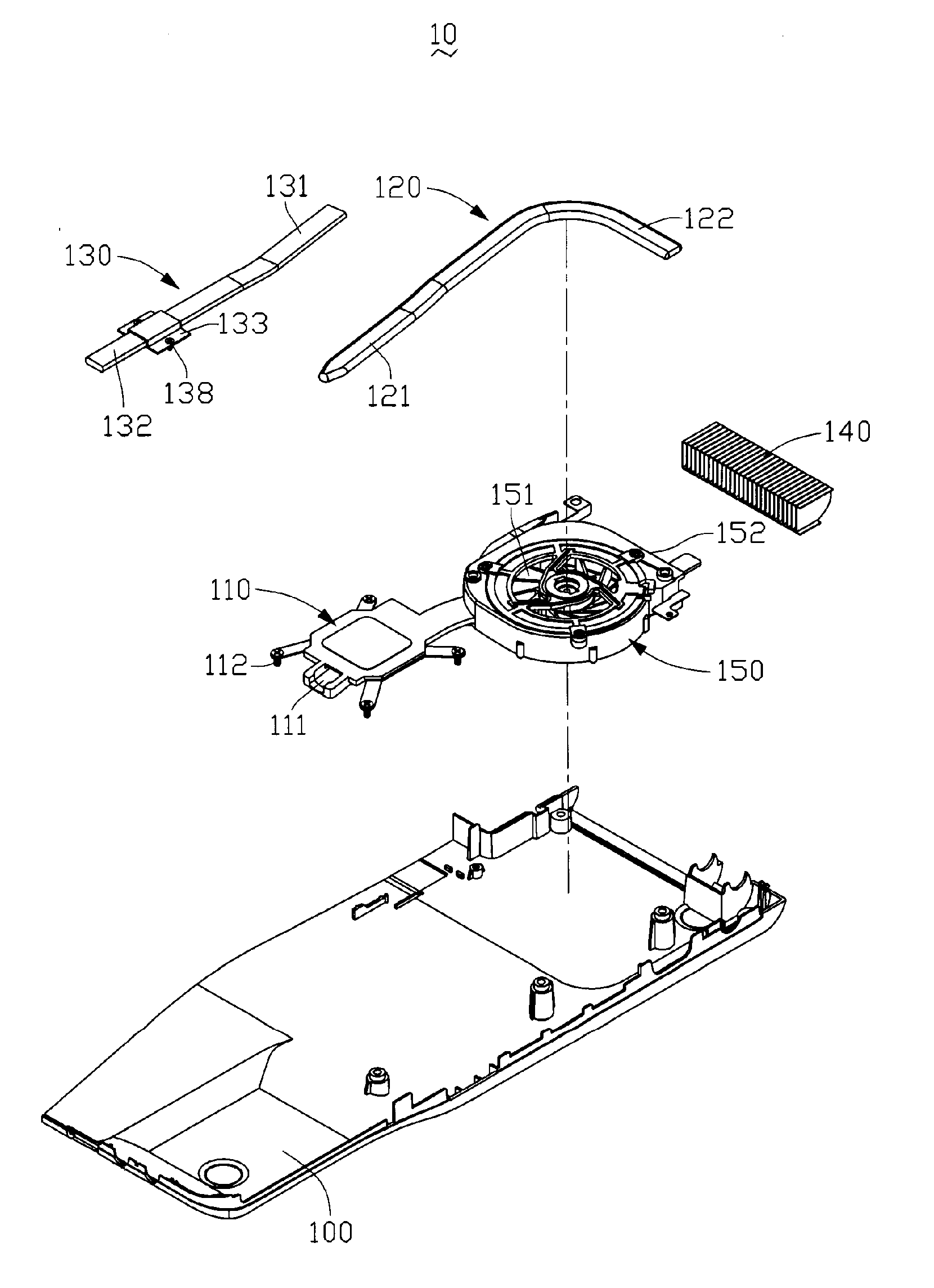
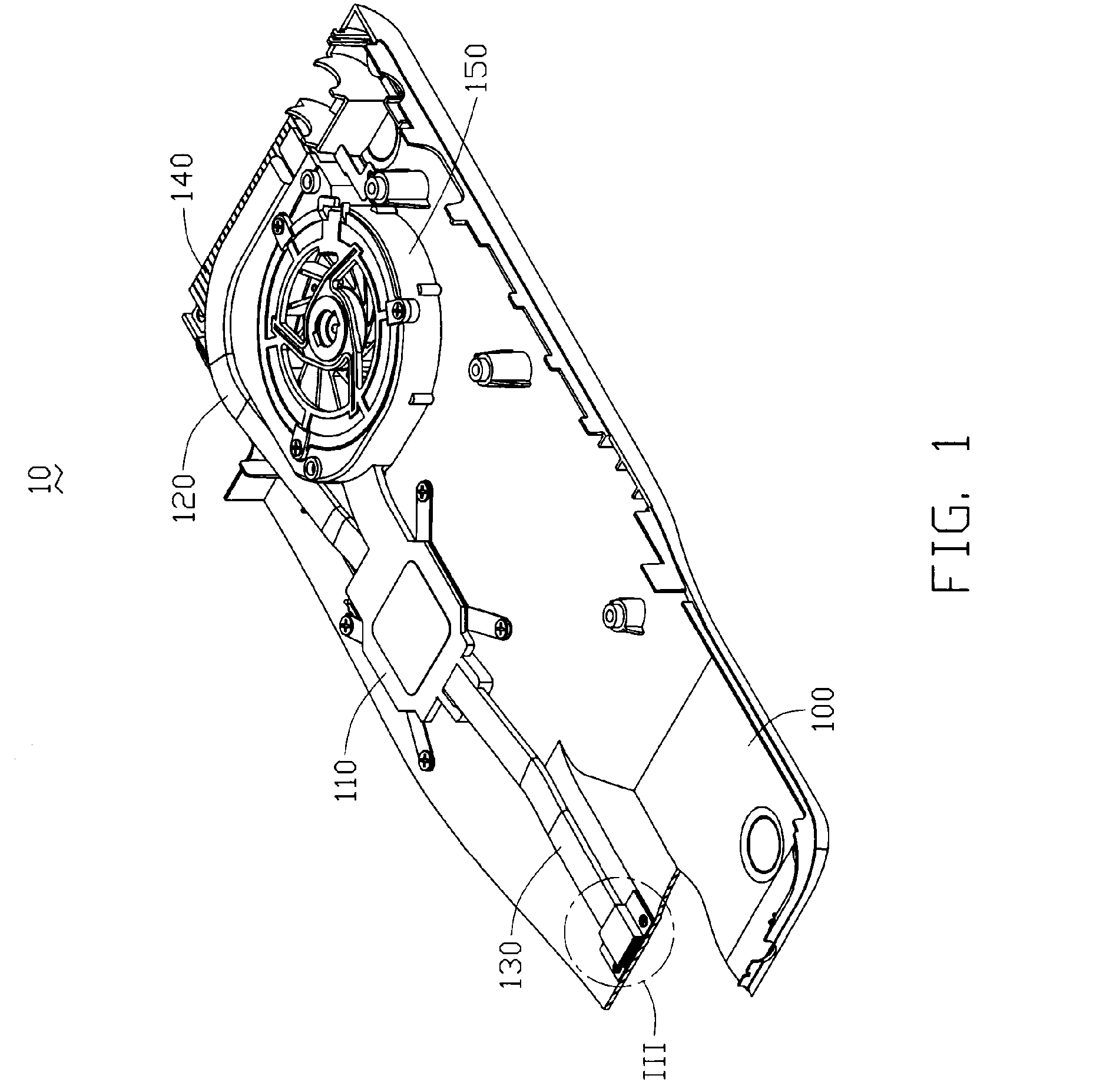
[0012]Referring to FIG. 1, a heat dissipation apparatus 10 according to a preferred embodiment of the present invention is shown. The heat dissipation apparatus 10, which is attached to a computer enclosure 100 having good heat conduction, includes a heat spreader 110 for thermally connecting with a heat generating electronic component (not labeled) in the computer enclosure 100, two heat pipes 120, 130, a fin assembly 140 contacting with the computer enclosure 100, and a centrifugal blower 150 producing an airflow over the fin assembly 140.

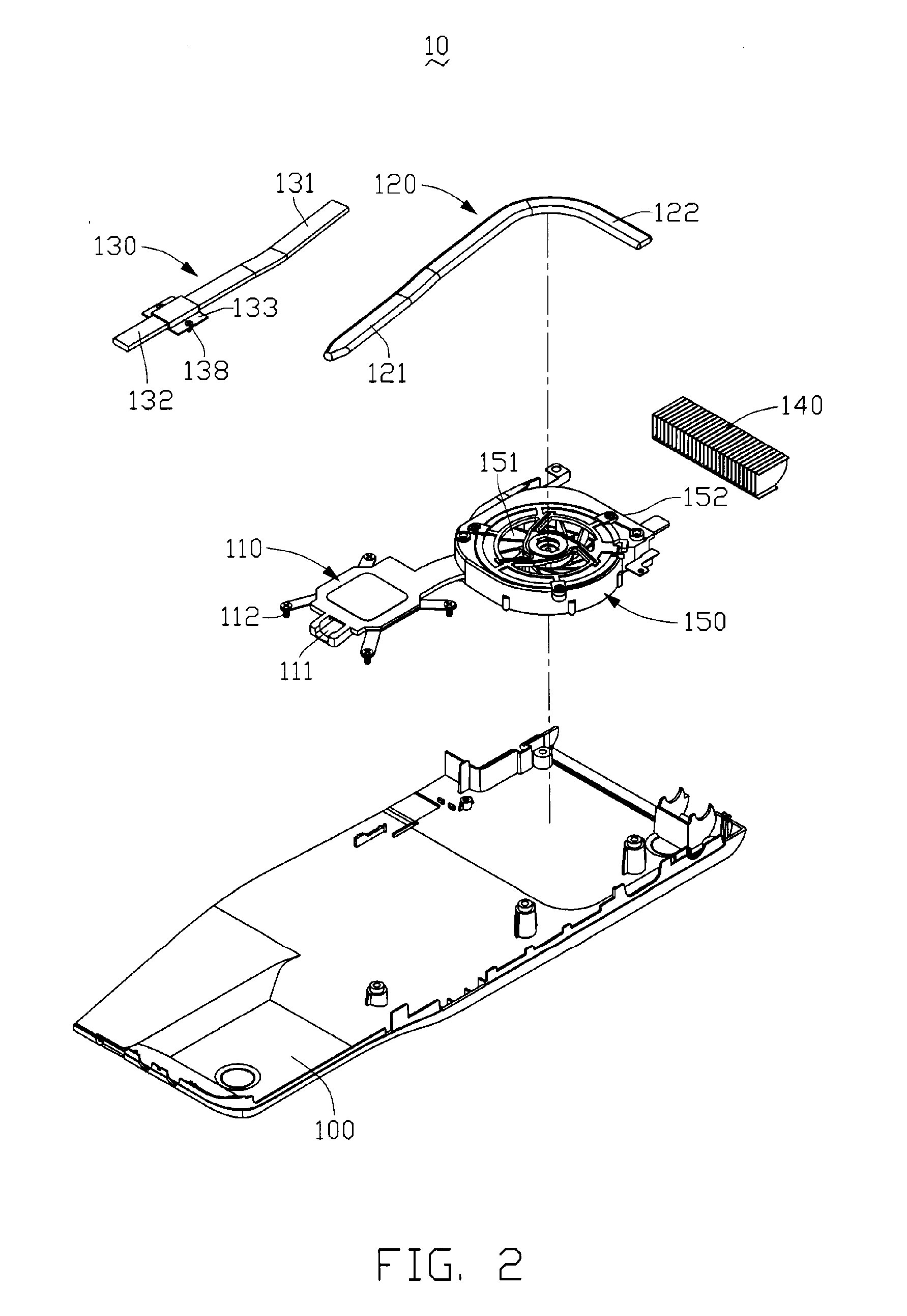
[0013]FIG. 2 shows the heat dissipation apparatus 10 in an exploded view. The computer enclosure 100 is typically made of a highly thermally conductive material such as copper, aluminum, magnesium or their alloys. The heat spreader 110, which is directly secured to the computer enclosure 100 via a plurality of first screws 112, thermally connects with the heat generating electronic component in the computer enclosure 100 and defines a receiving-g...


PUM


Abstract

A heat dissipation apparatus includes a metal enclosure for an electronic device, at least one heat pipe secured to the enclosure, a fin assembly secured to the enclosure, a centrifugal blower secured to the enclosure for promoting heat dissipation for the fin assembly. The heat pipe has an evaporating section thermally connecting with a heat generating electronic component within the enclosure, and first and second condensing sections respectively connecting with the enclosure and the fin assembly. The enclosure absorbs and dissipates heat generated by the heat generating electronic component. The heat dissipation surface area is increased and as a result the heat dissipation efficiency of the heat dissipation apparatus is improved.

Description

1. FIELD OF THE INVENTION[0001]The present invention relates generally to a heat dissipation apparatus, and more particularly to a heat dissipation apparatus for dissipating heat generated by heat generating electronic components enclosed in a system enclosure, wherein the apparatus has at least one heat pipe secured to the enclosure for dissipating heat via the enclosure.2. DESCRIPTION OF RELATED ART[0002]It is well known that heat is produced by electronic components such as integrated circuit chips during their normal operations. If the heat is not timely removed, these electronic components may overheat. Therefore, heat dissipation apparatuses are often used to cool these electronic components.[0003]As an example, a conventional heat dissipation apparatus generally includes a plate, a fin assembly having a plurality of fins, a fan creating an airflow over the fin assembly, and a heat pipe having an evaporating section for holding in thermal contact with a heat generating electro...

Claims


Application Information

Patent Timeline
Patent Type & Authority Applications(United States)
IPC IPC(8): H05K7/20F28D15/00H01L23/34
CPCF28D15/0233F28D15/0275H01L23/427H01L2924/0002H01L2924/00
Inventor CHENG, NIEN-TIENLIN, CHEN-SHEN
Owner HON HAI PRECISION IND CO LTD
Why Eureka
Try Eureka