
Multitrack curve-tilting vehicle, and method for tilting a vehicle

a multi-track, curve-tilting technology, applied in the field of curvetilting vehicles, can solve the problems of not being able to provide to the driver, not being able to exercise a sensitive control of vehicle tilt, and provoking startled reactions of the driver, and achieve good stability

Inactive Publication Date: 2007-08-23
GEISER FRIEDRICH
View PDF4 Cites 49 Cited by
  • Summary
  • Abstract
  • Description
  • Claims
  • Application Information

AI Technical Summary

Benefits of technology

[0019] It is a task of the invention, therefore, to provide a multitrack curve-tilting vehicle distinguished by a lateral tiltability that can be influenced intuitively by the driver and matches his expectations, both at higher and at lower speeds, while offering good stability under all driving conditions. It is another task of the invention to improve the generic multitrack curve-tilting vehicles known from the prior art, and more particularly the three-wheeled vehicles known from WO 97 / 27,071, with respect to their lateral tilting properties.

Problems solved by technology

In practice, however, problems are associated exactly with this transition zone from the two-wheel mode, that is, the state of free mobility of the two lateral wheel suspensions, to the three-wheel mode, that is, the state in which a free lateral tilting is prevented by blocking of the free mobility of the lateral wheel suspensions.
Because, an automatic active interference with the vehicle's free tiltability is perceived as unpleasant and strange by the driver, and will provoke startled reactions of the driver, sometimes dangerous.
It is an essential disadvantage of this system that independently of speed, between the tilt sensing system and the vehicle seat a coupling exists that may lead to dangerous situations, particularly at high speeds where an excessive active interference with the vehicle's tilt is undesirable.
It is not possible to provide to the driver the typical driving behavior of a two-wheeled vehicle, since vehicle tilt is achieved in an active way via the pendulum while the driver always is centrally poised on the vehicle, and he may influence the tilting behavior of the vehicle via a displacement of his center of gravity, only when judging that the angle of tilt of the vehicle is not sufficiently large.
In view of the fork's play that must be provided, it is not at all possible to exercise a sensitive control of vehicle tilt by weight shifts.
At these low speeds, self-stabilization of the vehicle that comes about more particularly through the gyroscopic action of the wheels is still not sufficient for a smooth straight forward motion of the vehicle.
A tilting of the vehicle by weight shifts of the driver is not possible in this mode, since the clutch is engaged and the arms cannot freely move relative to each other.
The multitrack curve-tilting vehicles of the prior art described above have the common problem that more particularly at low speeds, a balancing of the vehicle or a tilting as desired by the driver is possible to a degree only, or is perceived as unpleasant or strange by the driver.
When driven at low speeds or at rest, however, known multitrack curve-tilting vehicles are found to be problematic.
A use of the feet for stabilization of the vehicle is highly dubious at times, since the mass of some of these vehicles is too large for their safe stabilization, or their closed cabin will prohibit any use of the feet.
Tipping over may give rise to important injuries of the legs, arms, and head in particular.
An active tilting of the vehicle is perceived as unnatural and unpleasant by the driver, since generically a tilting sensor may trigger the active tilting, only after it has captured an inclined position or centrifugal force.
Tilting control via a tilting sensor is definitely problematic, primarily when driving an uneven road at low speeds not admitting free tiltability of the vehicle, where the stabilizing gyroscopic forces of the wheels are too small and the vehicle must be driven in the three-wheel mode.
It would be possible for the driver recognizing such a situation, for instance prior to driving over an incline, to manually preadjust the tilt by himself, but this possibility is found to be nonergonomic and hardly practical.
A further problem arises when entering a bend at low speeds.
However, this familiar driving behavior of motorcycles cannot be simulated with known multitrack curve-tilting vehicles at low speeds.
In the prior art, tangible tilting can only be initiated by active manipulation of an actuating unit by the driver or as a reaction to a centrifugal force or steering movement, so that it will not be possible to drive the vehicle by weight shifts like riding a motorcycle.
Known multitrack curve-tilting vehicles meet considerable problems of acceptance by drivers, since at higher speeds in the two-wheel mode they have completely different tilting properties than at lower speeds in the three-wheel mode, inasmuch as the driver may trigger a tilting by shifts of body weight only at higher speeds but not at low speeds.

Method used


Image

  • Multitrack curve-tilting vehicle, and method for tilting a vehicle
  • Multitrack curve-tilting vehicle, and method for tilting a vehicle
  • Multitrack curve-tilting vehicle, and method for tilting a vehicle

Examples


Embodiment Construction

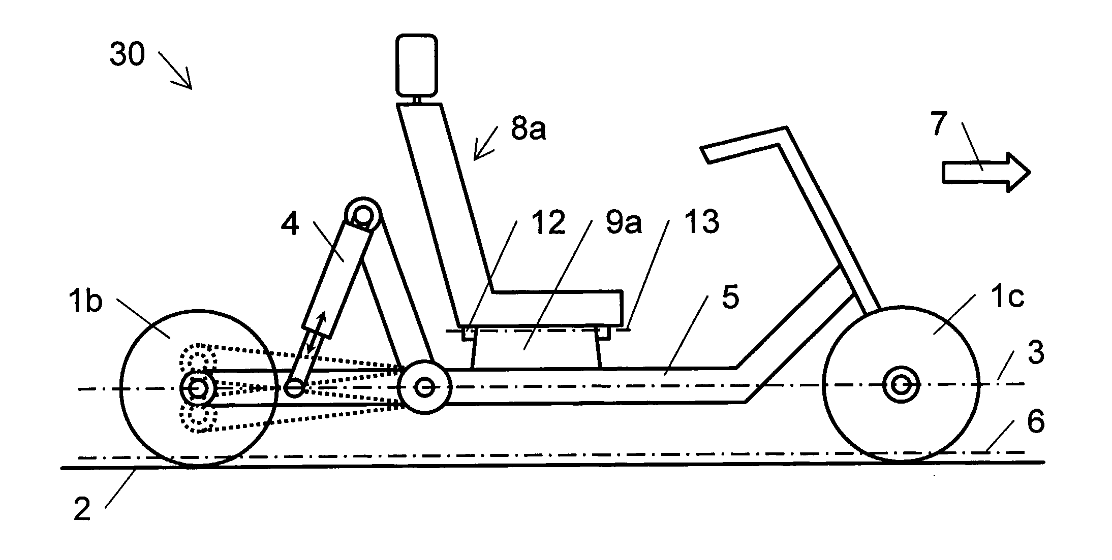
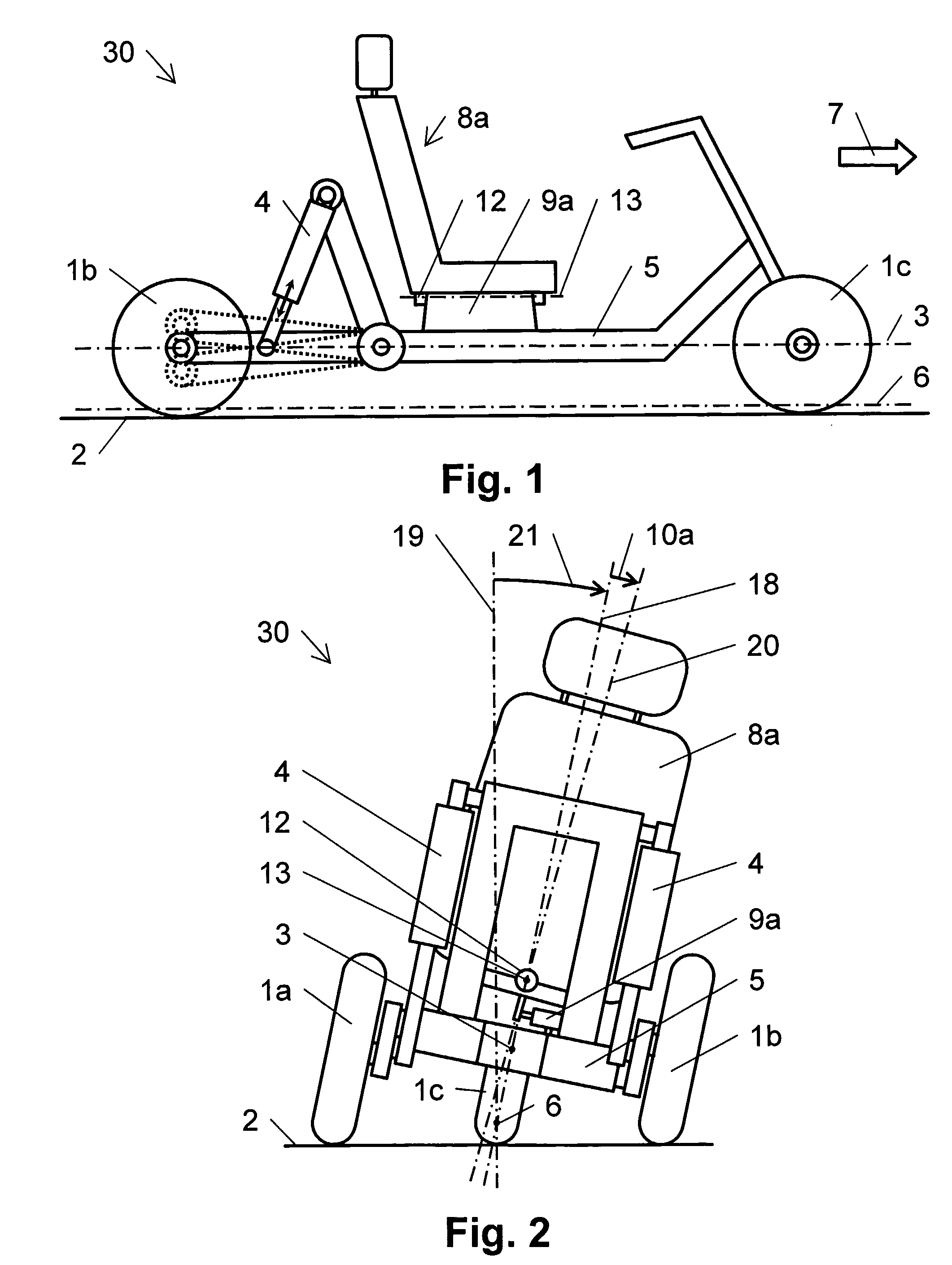
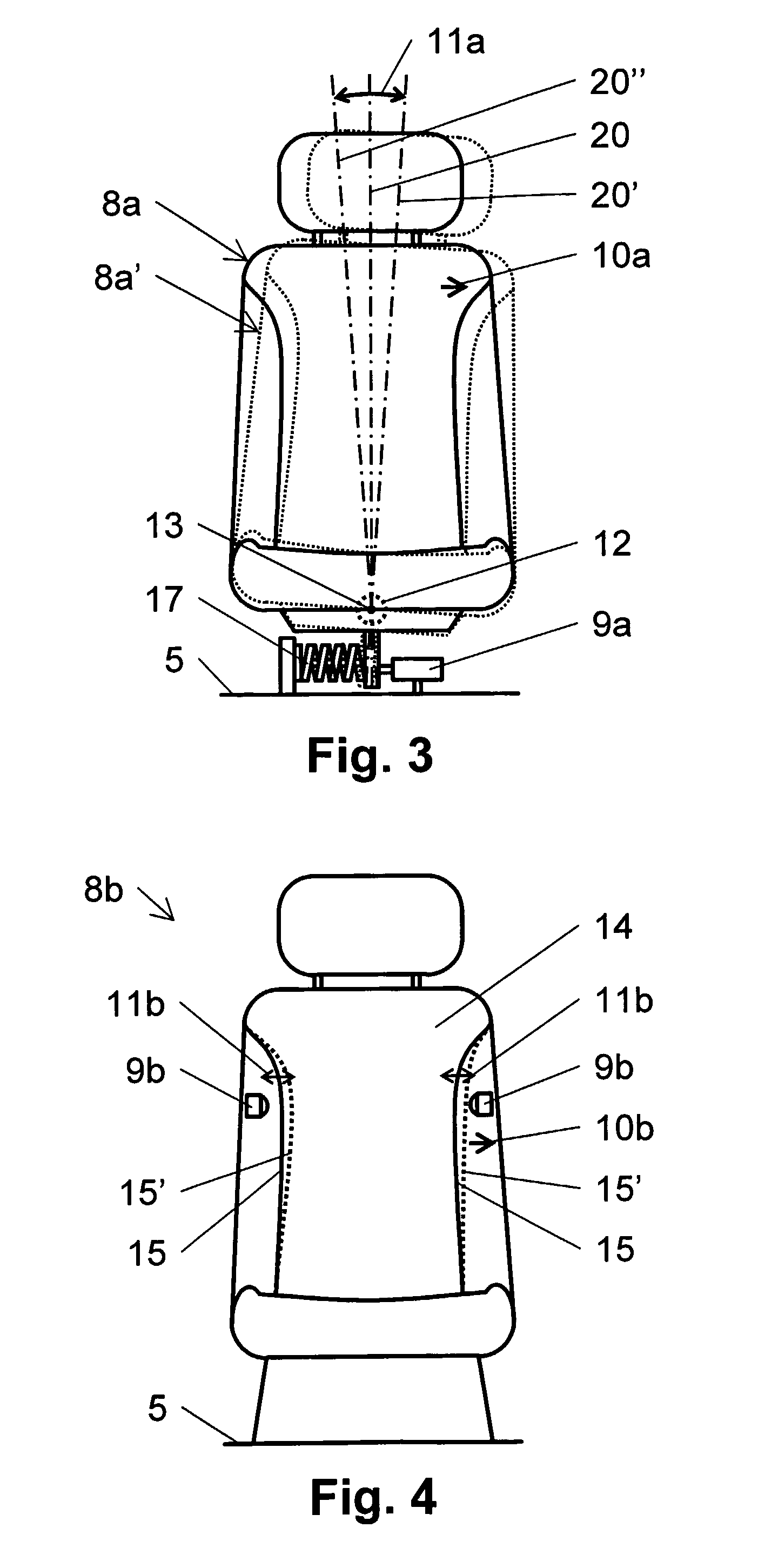
[0034] In FIGS. 1 and 2, one possible embodiment of the multitrack curve-tilting vehicle according to the invention is schematically represented in a lateral and in a rear view, respectively. The three-wheeled vehicle 30 represented comprises three supporting elements 1a, 1b, 1c resting on a ground 2 and formed as a front wheel 1c, a right-hand rear wheel 1b, and a left-hand rear wheel 1a. The front wheel 1c is steerable, and is centrally arranged in the vehicle's longitudinal axis 3, while the two lateral wheels 1a and 1b are mounted essentially symmetrically relative to the vehicle's longitudinal axis 3. The three-wheeled vehicle 30 has means 4 for laterally tilting the vehicle's frame 5 about a tilting axis 6 that runs essentially parallel to the vehicle's longitudinal axis 3, so that while traveling, more particularly in a bend or on sloping or uneven ground, the vehicle's center of gravity can be displaced in a direction perpendicular to the direction 7 of travel. The lateral t...


PUM


Abstract

A curve-tilting vehicle, e.g, a three-wheeled vehicle (30), including a laterally tilting device (4) at least one section (5) of the vehicle by a tilting axis (6) that runs substantially parallel to the longitudinal axis (3) of the vehicle such that the center of gravity of the vehicle can be displaced perpendicular to the direction of travel when driving, especially in curves or on a sloped or uneven ground. The vehicle includes at least one vehicle seat (8a) that is disposed in the tilting section (5) of the vehicle and is allocated to the driver who steers the vehicle. The vehicle further includes a detector (9a) for detecting a lateral force of the seat, which the body of the driver applies at least to one zone of the vehicle seat (8a) in a lateral direction (10a) extending perpendicular to the direction of travel. The lateral force of the seat may be detected using a pivotal spring-centered vehicle seat (8a). The detector (9a) is effectively connected to the lateral tilting includes (4) in such a way that lateral tilting occurs in accordance with the detected lateral force of the seat while the tilting speed is a function at least of the lateral force of the seat and the vehicle speed, the tilting speed increasing as the lateral force of the seat rises at a factor that decreases as the speed of the vehicle goes up. The invention further relates to a method for tilting such a vehicle.

Description

CROSS-REFERENCE TO RELATED APPLICATION [0001] This application is a National Phase of International Application Serial No. PCT / EP2005 / 001340, filed 10 Feb. 2005.BACKGROUND OF THE INVENTION [0002] 1. Field of the Invention [0003] The invention relates to a curve-tilting vehicle having means for laterally tilting at least one section of the vehicle about a tilting axis running essentially parallel to the vehicle's longitudinal axis, to the effect that while traveling, for instance in a bend or on sloping or uneven ground, the center of gravity of the vehicle can be displaced in a direction perpendicular to the direction of travel. The vehicle comprises at least one vehicle seat disposed on the tiltable section of the vehicle and intended for a driver steering the vehicle. The vehicle in general may be any multitrack motor or muscle-powered vehicle such as a road vehicle with wheels, a snowmobile with runners, or a watercraft with foils, having at least three points of support on a gro...

Claims


Application Information

Patent Timeline
IPC IPC(8): B62D61/06B60G21/00B60N2/02B60G17/019B60R21/01B62D9/02B62J99/00B62K5/027
CPCB60G17/01908B60G17/01925B60G2300/122B60G2300/45B60G2400/204B62K5/10B60G2400/96B60G2800/019B60N2/449B62D9/02B62K5/027B60G2400/62
Inventor GEISER, FRIEDRICH
Owner GEISER FRIEDRICH
Learn More