
Electromagnetic-wave shielding and light transmitting plate, manufacturing method thereof, and display panel

a technology of electromagnetic wave shielding and light transmitting plate, which is applied in the direction of instruments, optical elements, transportation and packaging, etc., can solve the problem that the electromagnetic wave shielding film comprising such a laminated film of metal foil/substrat film cannot have sufficient visibility, and achieves the effect of reducing weight, thickness and number of parts, improving productivity, and reducing cos

Inactive Publication Date: 2007-08-16
BRIDGESTONE CORP
View PDF9 Cites 13 Cited by
  • Summary
  • Abstract
  • Description
  • Claims
  • Application Information

AI Technical Summary

Benefits of technology

The present invention provides an electromagnetic-wave shielding and light transmitting plate that has excellent electromagnetic-wave shielding function and high antireflection effect with high transparency and visibility. The electromagnetic-wave shielding film comprises a transparent substrate film and a conductive foil bonded together with a transparent adhesive agent, and the foil has a light absorbing layer for antireflection on one surface. The surface roughening of the light absorbing layer provides high antireflection effect. The electromagnetic-wave shielding and light transmitting plate can be used in display panels to provide a distinct image with high contrast. The manufacturing method involves forming a light absorbing layer on a conductive foil, treating the surface with surface roughening, bonding the foil to a transparent substrate film, pattern etching the foil, and applying a transparent pressure-sensitive adhesive to the etched surface.

Problems solved by technology

An electromagnetic-wave shielding film comprising such a laminated film of the metal foil / the substrate film can not have sufficient visibility because light is reflected at the surface of the metal foil.

Method used


Image

  • Electromagnetic-wave shielding and light transmitting plate, manufacturing method thereof, and display panel
  • Electromagnetic-wave shielding and light transmitting plate, manufacturing method thereof, and display panel
  • Electromagnetic-wave shielding and light transmitting plate, manufacturing method thereof, and display panel

Examples


Embodiment Construction

[0056] Embodiments of the present invention will be described in detail with reference to the attached drawings.

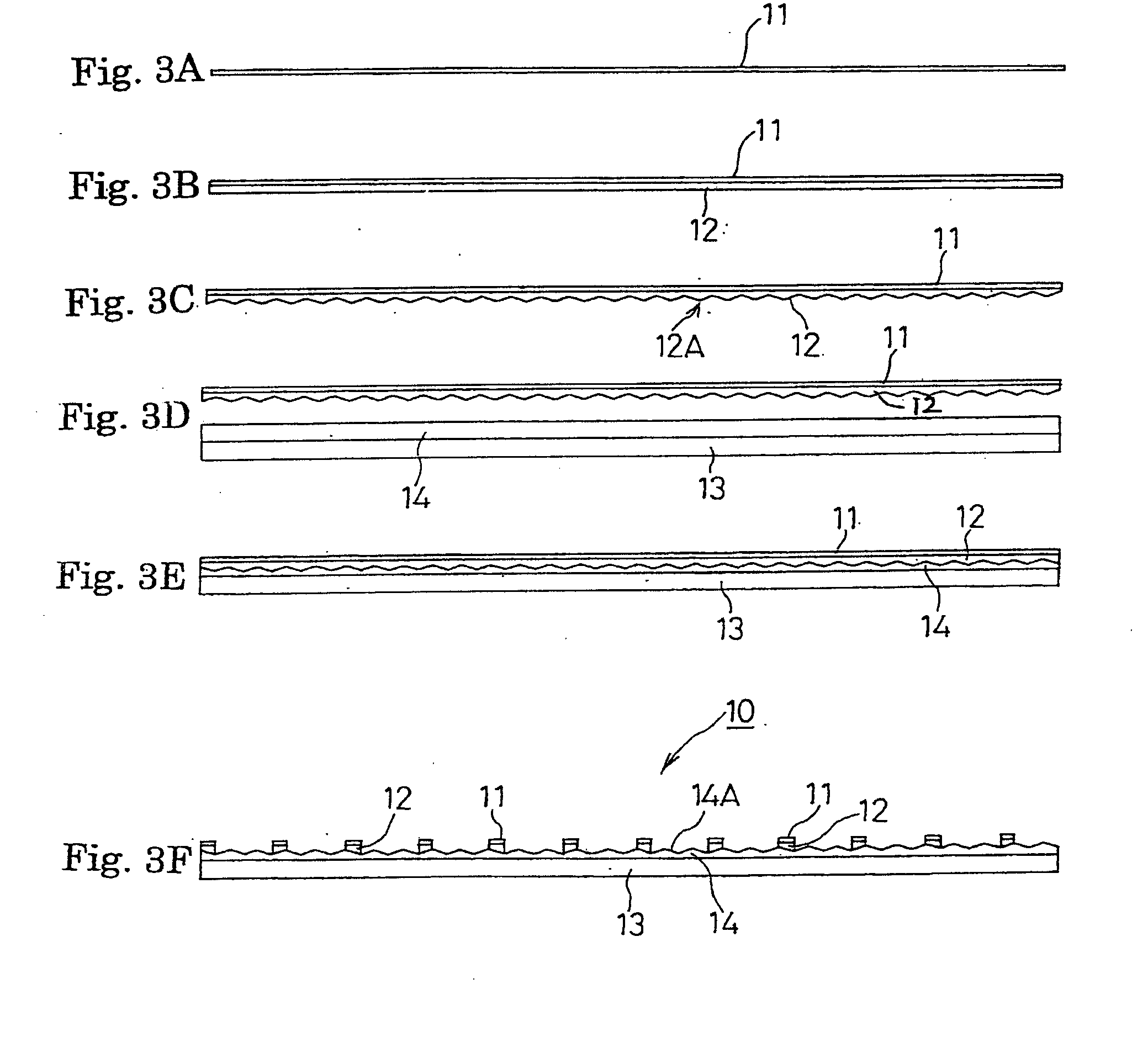
[0057] With reference to FIGS. 3A-3F, an exemplary method of manufacturing an electromagnetic-wave shielding film to be used in an electromagnetic-wave shielding and light transmitting plate of the first aspect of the present invention will be described.

[0058] For example, a copper foil 11 is prepared as a conductive foil (FIG. 3A) and a light absorbing layer 12 is formed on one surface of the copper foil 11 (FIG. 3B). As a forming method of this light absorbing layer 12, there is a method of making a film of a copper alloy such as Cu—Ni and, after that, blackening a surface of the film by treatment with acid or alkali. The blackened surface subjected to this surface treatment is roughened. The surface roughness Rz can be controlled according to the treatment condition. Alternatively, the light absorbing layer 12 can be formed by applying a light absorbing ink onto the c...


PUM

PropertyMeasurementUnit
surface roughness Rzaaaaaaaaaa
diameteraaaaaaaaaa
light transmittanceaaaaaaaaaa

Abstract

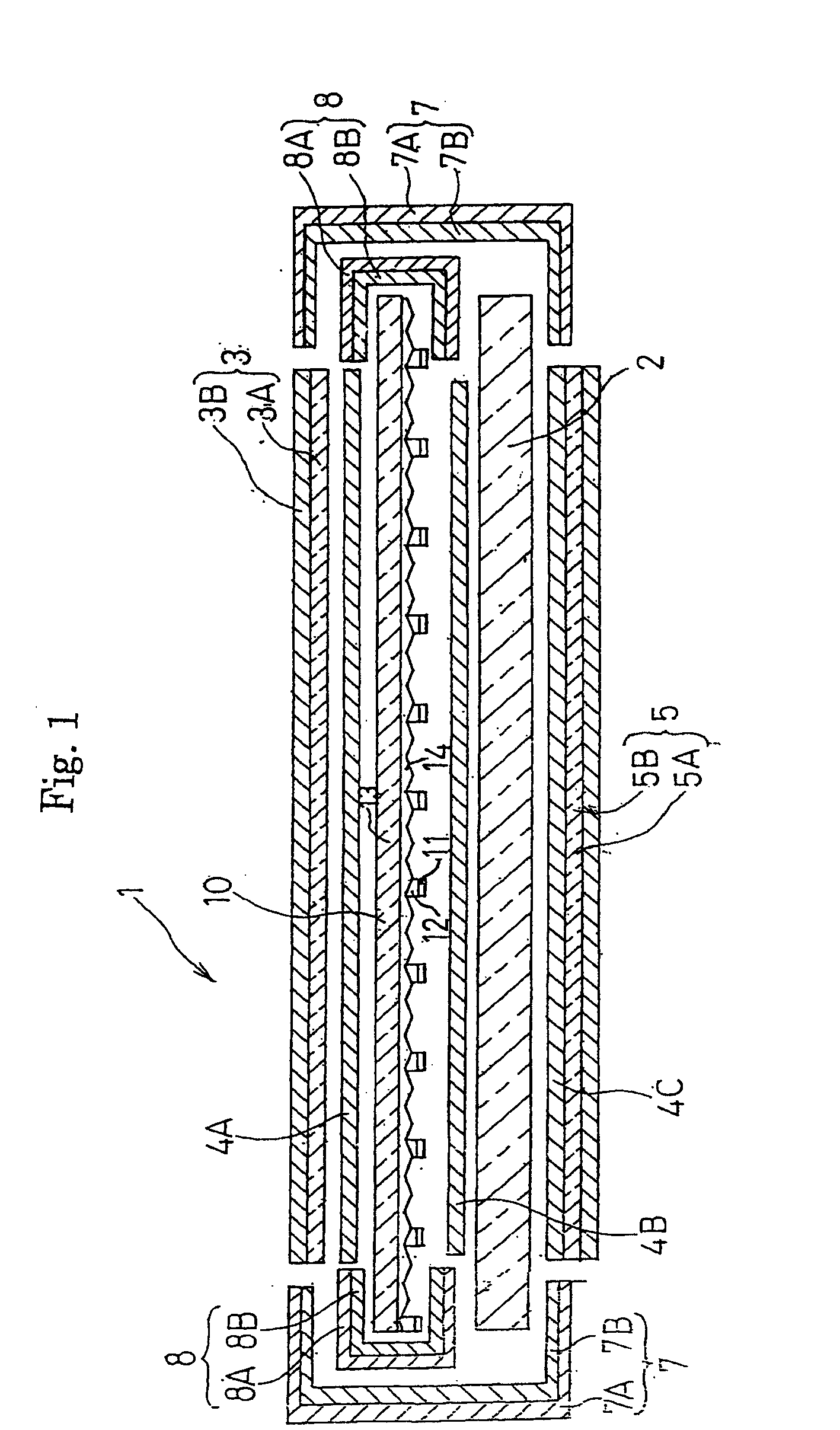
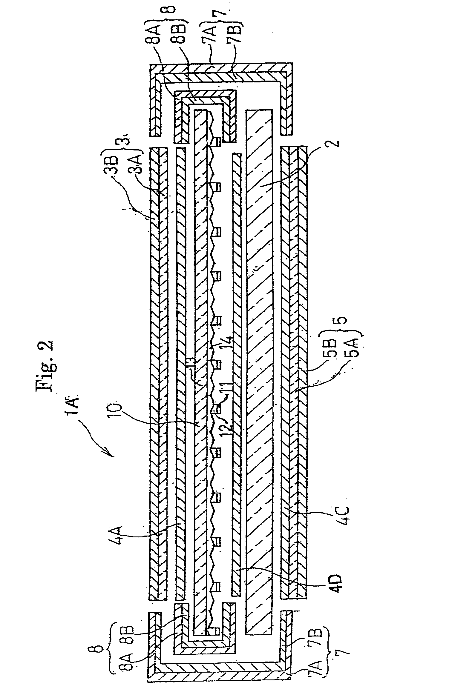
An electromagnetic-wave shielding and light transmitting plate 1 comprising an antireflection film 3, an electromagnetic-wave shielding film 10, a transparent substrate 2, and a near-infrared ray blocking film 5, wherein they are laminated and united by using intermediate adhesive layers 4A, 4B and a pressure-sensitive adhesive 4C, and the peripheries thereof are covered by a conductive sticky tape 7. The electromagnetic-wave shielding film 10 has a conductive foil 11 formed by pattern etching on a substrate film 13, is processed to have antireflection function by forming a light absorbing layer 12 on the conductive foil 11, and is subjected to a matting process to form small irregularities by roughening the surface of the light absorbing layer 12. A display panel is manufactured by bonding this electromagnetic-wave shielding film 10 to the front surface of a plasma display panel body. Accordingly, an electromagnetic-wave shielding and light transmitting plate and a display panel can be obtained which not only have excellent electromagnetic-wave shielding function but also provide high antireflection effect and have high level of transparency and high level of visibility, thereby providing distinct images.

Description

CROSS REFERENCE TO RELATED APPLICATION [0001] This is a divisional application of the U.S. application Ser. No. 10 / 476,852 filed on Nov. 6, 2003, which is a National Stage entry of PCT / JP02 / 04423 filed May 7, 2002, which claims benefit to JP 2001-146843, JP 2001-146844, JP 2001-146845, JP 2001-146846 and JP 2001-146847 all of which were filed on May 16, 2001. The prior applications are hereby incorporated by reference as if fully set forth herein.FIELD OF THE INVENTION [0002] The present invention relates to an electromagnetic-wave shielding and light transmitting plate, a manufacturing method thereof, and a display panel. More particularly, the present invention relates to an electromagnetic-wave shielding and light transmitting plate which has excellent electromagnetic-wave shielding function, a high level of transparency, and a high level of visibility so that it can be suitably used as a front filter for a PDP (plasma display panel) and a manufacturing method thereof and further...

Claims


Application Information

Patent Timeline
Patent Type & Authority Applications(United States)
IPC IPC(8): B44C1/17B32B3/00B32B15/08G02B1/11G02B1/12H01J5/02H01J37/16H05K9/00
CPCB32B3/00B32B15/08G02B1/11G02B1/12G02B5/204H01J5/02Y10T156/10H01J2211/446H05K9/0096Y10T428/24851Y10T428/24917Y10T428/24802H01J37/16
Inventor YOSHIKAWA, MASATOKITANO, TETSUOKOBAYASHI, TAICHIKOTSUBO, HIDEFUMI
Owner BRIDGESTONE CORP
Learn More