
Microfluidic mixing and analytical apparatus

a technology of microfluidic mixing and analytical equipment, which is applied in the direction of analytical tools using chemical indicators, laboratory glassware, instruments, etc., can solve the problems of inability to efficiently automate and integrate methods, inability to meet the needs of efficient automation and integration, and limitations of their use,

Active Publication Date: 2007-08-09
PERKINELMER HEALTH SCIENCES INC
View PDF19 Cites 148 Cited by
  • Summary
  • Abstract
  • Description
  • Claims
  • Application Information

AI Technical Summary

Benefits of technology

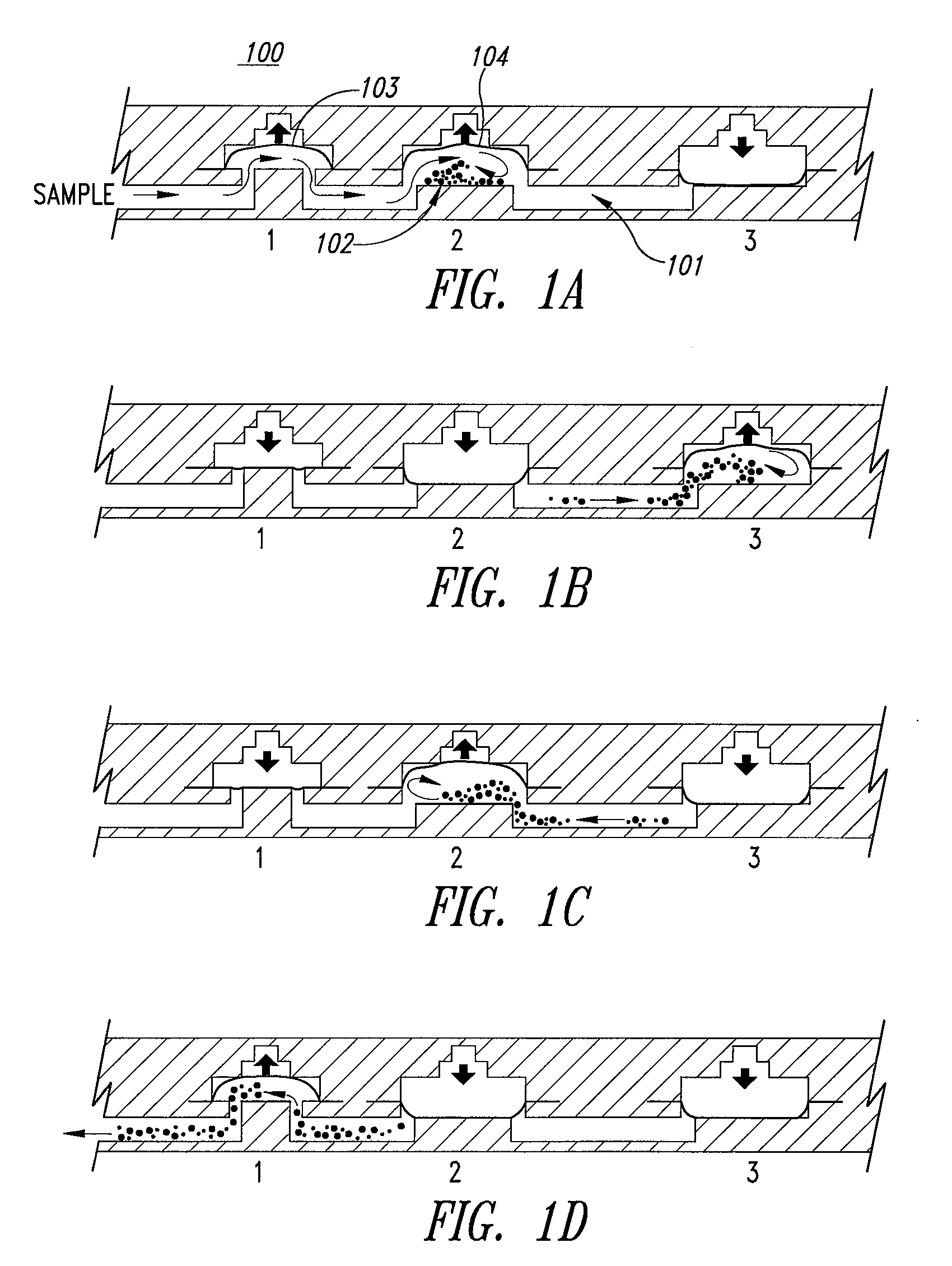
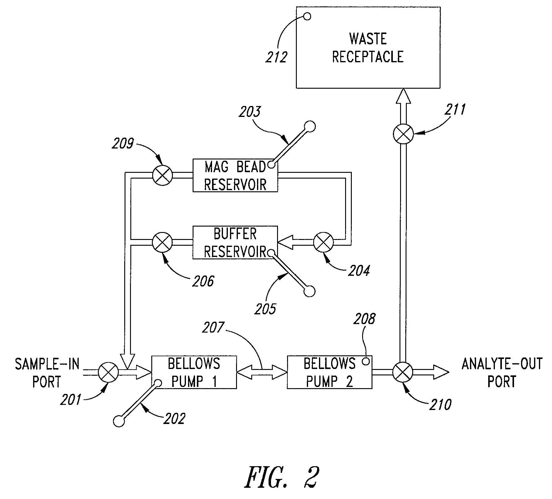
[0019] A preferred embodiment disclosed herein is a pair of bellows pumps configured for efficient mixing of particles in suspension at a microfluidic scale. An aperture fluidically connects the bellows pump chambers. As described below, reciprocating pump flow of the suspension through the aperture promotes turbulent mixing and molecular collision of affinity capture particles with ligands as an aid in capture of useful cells and molecules. Such mixing elements provide an alternative for mixing that does not use a vent and enables efficient mixing of small or larger volumes containing particles such as magnetic beads from 0.2 to 100 um in size, more preferably from 1.5 to 50 um, and other beads such as latex and ion exchange polymers. These paired bellows pump mixing elements are combined with other microfluidic structures in microfluidic devices and apparatuses.

Problems solved by technology

These methods are not generally amenable to efficient automation and integration with subsequent assay steps, especially in a manner compatible with the development of point of care testing.
However, limitations of their use occur since these large particles are not colloidal, and do not diffuse.
Tube methods exhibit inconsistent and long (15-90 minute) mixing and are not readily automated and integrated within an assay method.
However, for larger analytes such as cells, bacteria, viral particles, and for macromolecular complexes and linear polymers, diffusional mixing is slow and processes for capture or depletion of these species require prolonged incubation.
Diffusional limits on mixing thus present a problem in microfluidic devices where bulk mixing or comminution of a sample and reagents or beads is required.
This problem has not been fully solved and methods, devices and apparatuses for improving the mixing arts are being actively sought.

Method used


Image

  • Microfluidic mixing and analytical apparatus
  • Microfluidic mixing and analytical apparatus
  • Microfluidic mixing and analytical apparatus

Examples


example 1

Transition to Turbulent Flow

[0119] A classical way to detect the pipe-flow transition for a fluid is to inject a stream of dye into the moving fluid and to observe the wavering of the dye stream as it flows down the pipe. In the present experiment with particles, direct visualization of particle motion is also a very straightforward way of observing laminar flow and turbulence. Motion in the laminar regime is characterized by parallel particle trajectories, and motion in a turbulent transitional “puff” represents strong mixing in the radial direction. Similar observations can also be made as laminar flow breaks up as fluid exits from a pipe into a bulk fluid receiving vessel.

[0120] Flows in microfluidic structures are laminar and allow mixing by diffusion along boundary layers and interfaces (a phenomenon described in detail in U.S. Pat. No. 5,972,710 to Wiegl and co-assigned). However, such phenomena present a problem in microfluidic devices where bulk mixing or comminution of a ...

example 2

CD45 Depletion using a Dual Bellows Mixing Device

Experimental Cartridge Protocol:

[0131] White cells were isolated from blood 5 mL with a 5 min room temperature lysis using Gentra RBC lysis solution. After two washes with phosphate buffered saline (PBS) the white blood cell (WBC) pellet was resuspended in 1 ml of PBS. About 10,000 SW480 cells (Cd45+) in 100 uL buffer were added to 100 ul of the resuspended WBC pellet and the mixture was transferred to a dual bellows mixing cartridge of the present invention. All reagents and apparatus were chilled to 4° C. for the experiment. CD45 affinity capture magnetic beads 100 uL (Dynal MyOne®, Cat No. 111.53, 4×10⁸ beads / mL) were then added. Bead population in the mixer was thus about 4×10⁷ beads in a volume of 200 uL, with a cell:bead ratio of about 1:4000. The sample:bead suspension was mixed for four minutes using an automated apparatus compatible with the cartridge. A magnet was applied to the cartridge to trap the beads and the deplete...

example 3

Capture of E coli with O157:H7 Serotype-Specific Antibody

Affinity Capture Bead Preparation:

[0134] Dynal MyOne® Tosylactivated beads were obtained from the manufacturer (Dynal ASA, Oslo Norway) and derivatized with Anti-O157:H7 antibody (US Biologicals, Swampscott Mass.) by the suggested protocol. Per 1 mg of beads, 40 mg of antibody was used. Bead diameter is 1.08 um.

Dual Bellows Pump Mixing and Capture Device Description:

[0135] The mixing and capture cartridge tested had three parallel dual bellows pump mixing devices and supporting fluidic circuitry, so that three experiments could be run side-by-side in the apparatus. Each mixing device was provided with a pipet port, a pair of bellows pumps with interconnecting aperture, a fill port for magnetic beads, and pneumatic pulse actuation ports for the mixing chamber and valves. The device was placed into a microFlow™ manifold (Micronics, Inc. Redmond Wash.) apparatus so that the microfluidic valves and actuation lines could be c...


PUM

PropertyMeasurementUnit
Lengthaaaaaaaaaa
Lengthaaaaaaaaaa
Lengthaaaaaaaaaa

Abstract

Disclosed herein is a device comprising a pair of bellows pumps configured for efficient mixing at a microfluidic scale. By moving a fluid sample and particles in suspension through an aperture between the paired bellows pump mixing chambers, molecular collisions leading to binding between the particles and ligands in the sample are enhanced. Such devices provide an alternative for mixing that does not use a vent and can be used with a variety of particles in suspension such as magnetic beads to capture or purify useful cells and molecules.

Description

CROSS-REFERENCE TO RELATED APPLICATION [0001] This application claims the benefit under 35 U.S.C. §119(e) of U.S. Provisional Patent Application No. 60 / 740,697 filed Nov. 30, 2005, which provisional application is incorporated herein by reference in its entirety.BACKGROUND OF THE INVENTION [0002] 1. Field of the Invention [0003] The present invention relates generally to microfluidic devices for mixing suspensions of affinity capture beads in fluidized biological samples, and for apparatuses and methods for ligand capture, depletion, preconcentration, washing, and labeling, followed by analysis, by means of affinity capture beads. [0004] 2. Description of the Related Arts [0005] Biological analytes of relevance to clinical, biological, or environmental testing frequently are found at low concentrations in complex fluid mixtures. It is important to capture, concentrate, and enrich the specific analyte away from background inhibitory or interfering matrix components that can limit the...

Claims


Application Information

Patent Timeline
IPC IPC(8): B01L3/02
CPCB01F11/0071G01N2035/00564B01L3/502723B01L3/50273B01L3/502738B01L3/502761B01L2300/0816B01L2400/0481B01L2400/0655C12M23/16C12M23/42C12M25/16C12M29/10G01N2035/00544B01F13/0059B01F31/65B01F33/30
Inventor CLEMMENS, JOHNBATTRELL, C. FREDERICKGERDES, JOHNHOEKSTRA, DENISE MAXINE
Owner PERKINELMER HEALTH SCIENCES INC
Learn More