
Surface-emitting laser light source using two-dimensional photonic crystal

a laser light source and photonic crystal technology, applied in the direction of lasers, laser optical resonators, semiconductor lasers, etc., can solve the problems of inability to obtain a single-lobed beam profile with the laser light source, the the anti-symmetric mode of light cannot be extracted in the direction perpendicular to the surface, etc., to achieve the effect of lowering the degree of in-plan

Active Publication Date: 2007-08-02
ROHM CO LTD +1
View PDF2 Cites 22 Cited by
  • Summary
  • Abstract
  • Description
  • Claims
  • Application Information

AI Technical Summary

Benefits of technology

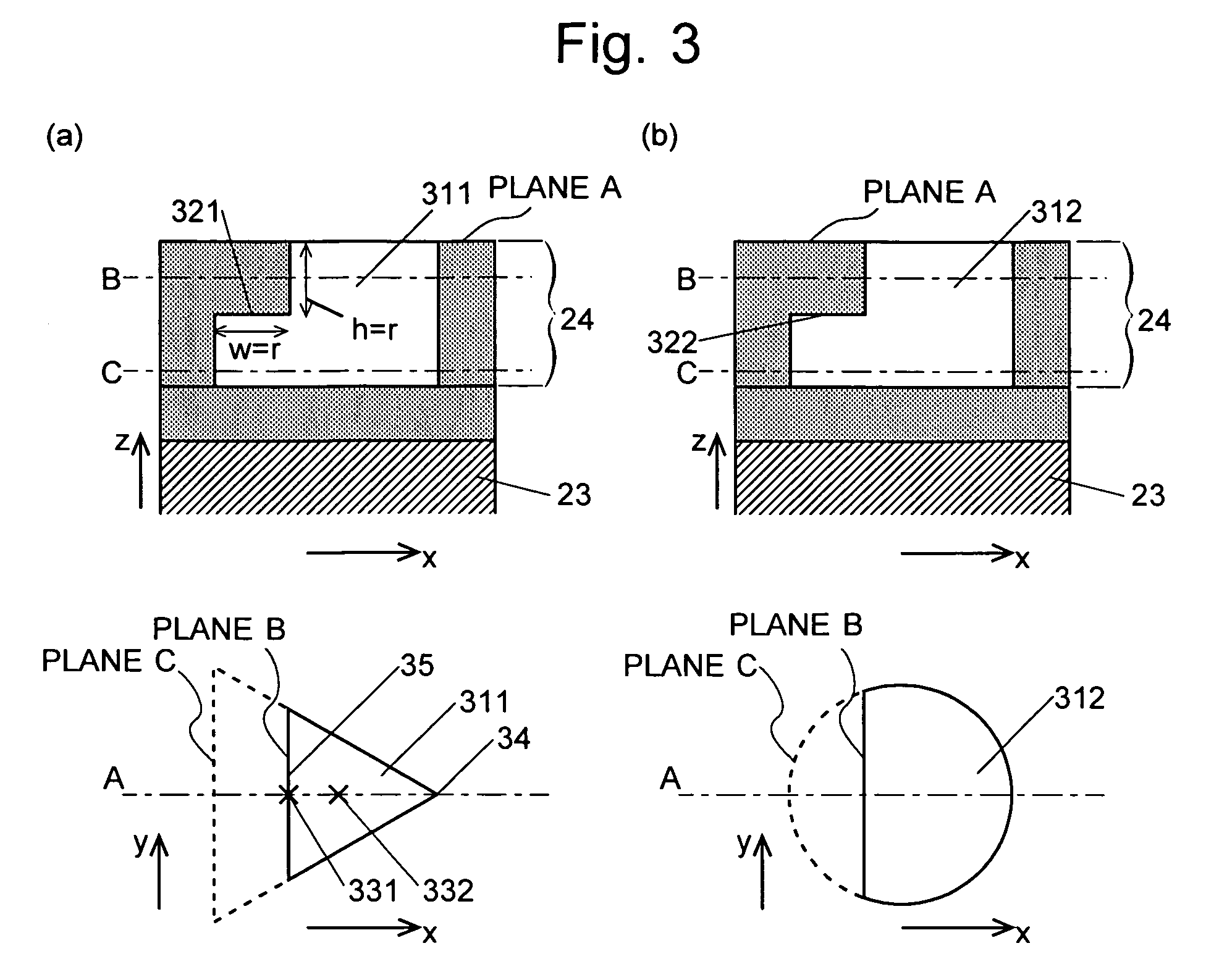
[0022] In the two-dimensional photonic crystal used in the present invention, which is constructed as described above, the periodic structure of the modified refractive index areas within the two-dimensional photonic crystal has a lower degree of symmetry on the emission side than on the active layer side. In the surface-emitting laser light source according to the present invention, the x-component and the y-component of the electric field are the main components within the active layer. However, the z-component of the electric field within the two-dimensional photonic crystal (i.e. the component in the direction perpendicular to the two-dimensional photonic crystal) on the emission side is larger than that on the active layer side. Therefore, the time-averaged intensity of the electric field including the x-direction and the y-direction on the emission side is larger than that on the active layer side. Making the modified refractive index area less symmetric on the emission side than on the active layer side weakens the light-confining effect of the two-dimensional photonic crystal, so that the laser light is easier to be emitted to the outside.
[0023] Since the center of gravity of the plane shape of the modified refractive index area on the active layer side is displaced from that on the emission side in the in-plane direction, the above two-dimensional photonic crystal does not have rotational symmetry around an axis perpendicular to the body material. Thus, the crystal has a low degree of symmetry in the in-plane direction. In a laser light source using such a two-dimensional photonic crystal, the emitted light of the anti-symmetric mode is not canceled out even in the central area of the two-dimensional photonic crystal, so that the beam profile is closer to the single-lobed shape. The lack of rotational symmetry makes it possible to extract a linearly polarized laser light, as explained earlier.
[0024] There have been some conventional studies (e.g. Patent Document 3) that have proposed the technique of lowering the degree of symmetry in the in-plane direction of the modified refractive index area in order to extract a linearly polarized light whose beam profile is close to the single-lobed shape. The present invention has introduced the new technical idea of changing the shape also in the direction perpendicular to the plate-shaped body material to further lower the degree of symmetry in the in-plane direction. This design provides a higher degree of freedom to control the shape of the modified refractive index areas.
[0026] In providing the difference in the plane shape of the modified refractive index area between the surface of the active layer side and that of the emission side, it is possible to design the shape (i.e. the plane shape inside the body material) between the two surfaces so that it changes along a linear or step-like profile. The step-like profile is easier to manufacture.
[0027] In addition to the above-described techniques of lowering the degree of in-plane symmetry, it is possible to appropriately choose the plane shape on the active layer side and / or the emission side to further lower the in-plane symmetry. For example, the plane shapes on the active layer side and the emission side may be an equilateral triangle or an ellipse. These shapes can create a clearer single lobe in the beam profile and improve the degree of linear polarization.
[0029] The modified refractive index area may preferably consist of holes, because this design provides a larger difference in refractive index from that of the body material and is easier to manufacture. However, if the two-dimensional photonic crystal needs to be fused with another layer at a high temperature during the manufacturing process, it is possible to create the modified refractive index areas by embedding certain members into the body material to prevent the modified refractive index areas from being deformed during the fusing process.

Problems solved by technology

However, the anti-symmetric mode of light cannot be extracted in the direction perpendicular to the surface.
However, it is impossible to extract the light from the center of the two-dimensional photonic crystal in the direction perpendicular to the surface because the degree of symmetry is high at the center.
However, Patent Document 2 includes no discussion about the beam profile; it is impossible to obtain a single-lobed beam profile with the laser light source disclosed in Patent Document 2.

Method used


Image

  • Surface-emitting laser light source using two-dimensional photonic crystal
  • Surface-emitting laser light source using two-dimensional photonic crystal
  • Surface-emitting laser light source using two-dimensional photonic crystal

Examples


embodiment

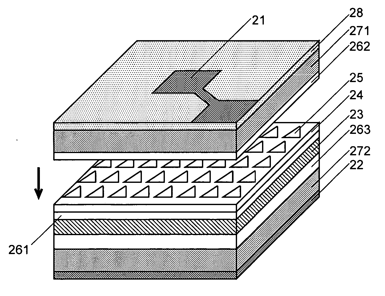
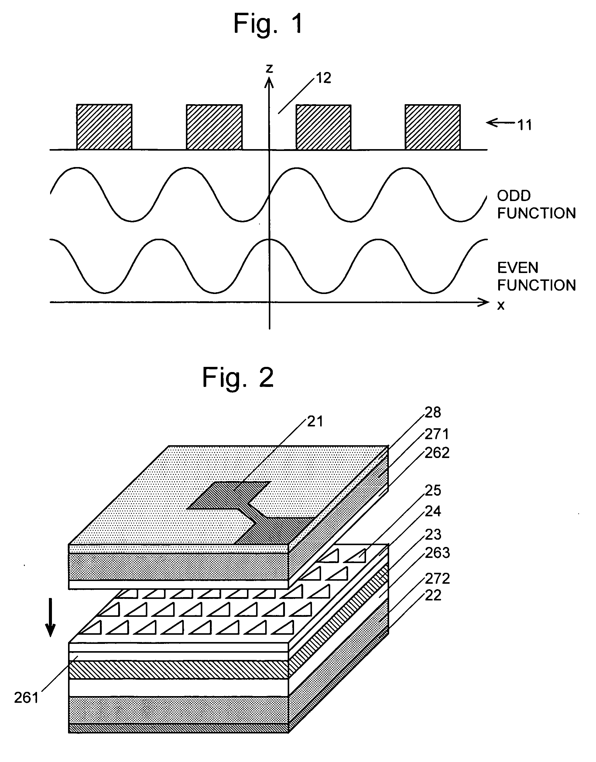
[0051] An embodiment of the surface-emitting laser light source using a two-dimensional photonic crystal according to the present invention is described with reference to FIG. 2. An active layer 23 made of Indium Gallium Arsenide (InGaAs) / Gallium Arsenide (GaAs) and having multiple-quantum wells (MQW) is provided between the anode 21 and the cathode 22. A two-dimensional photonic crystal layer 24 made of p-type GaAs is formed on the active layer 23 via a spacer layer 261, which is also made of p-type GaAs. The two-dimensional photonic crystal layer 24 consists of a plate member having holes 25 periodically arranged in a square lattice pattern. In the present embodiment, the spacer 261 and the two-dimensional photonic crystal layer 24 are integrally created as a single layer, in which the holes 25 are present only in the upper portion corresponding to the two-dimensional photonic crystal layer 24. A spacer layer 262 made of p-type GaAs, a cladding layer 271 made of p-type AlGaAs and ...


PUM


Abstract

The present invention intends to provide a surface-emitting laser light source capable of generating a linearly polarized laser light having a single-lobed beam profile that takes the largest intensity value in its central area. A two-dimensional photonic crystal consisting of a plate member 31 with holes 311 or 312 arranged in a square lattice pattern is provided on one side of an active layer 23. The hole 311 or 312 is designed so that its plane shape on the emission side (plane “B”) is smaller than that on the active layer side (plane “C”). The center of gravity of the shape on plane “B” is displaced from that of the shape on plane “C” in the in-plane direction. This design lowers the degree of the in-plane symmetry of the two-dimensional photonic crystal, so that a linearly polarized laser light having a single lobe is obtained.

Description

TECHNICAL FIELD [0001] The present invention relates to a surface-emitting laser light source for emitting laser light in a direction perpendicular to the surface of a flat light source. BACKGROUND ART [0002] Conventional laser light sources include a Fabry-Perot laser light source, which uses a Fabry-Perot resonator, and a distributed feedback (DFB) laser light source, which uses a diffraction grating. These types of laser light sources produce an oscillation of laser light by amplifying light of a predetermined wavelength through resonation or diffraction. [0003] In recent years, new types of laser light sources using a photonic crystal have been developed. A photonic crystal consists of a dielectric body material in which an artificial periodic structure is created. Usually, the periodic structure is created by providing the body material with a periodic arrangement of areas whose refractive index differs from that of the body material (this area is called the “modified refractiv...

Claims


Application Information

Patent Timeline
IPC IPC(8): H01S5/00H01S3/04H01S5/183H01S5/185H01S5/187
CPCH01S5/10H01S5/105H01S2301/18H01S5/187H01S2301/14H01S5/18H01S5/11H01S5/185H01S5/00H01S5/183
Inventor NODA, SUSUMUMIYAI, EIJIONISHI, DAI
Owner ROHM CO LTD
Learn More