
AlRu Sputtering Target and Manufacturing Method thereof

a technology of sputtering target and manufacturing method, which is applied in the direction of electrolysis components, vacuum evaporation coatings, coatings, etc., can solve the problems of low yield ratio, high content of oxygen, and target material is not suitable, so as to prevent or suppress the generation of particles, reduce oxygen content, and ensure stability and low cos

Inactive Publication Date: 2007-08-02
JX NIPPON MINING & METALS CO LTD
View PDF9 Cites 7 Cited by
  • Summary
  • Abstract
  • Description
  • Claims
  • Application Information

AI Technical Summary

Benefits of technology

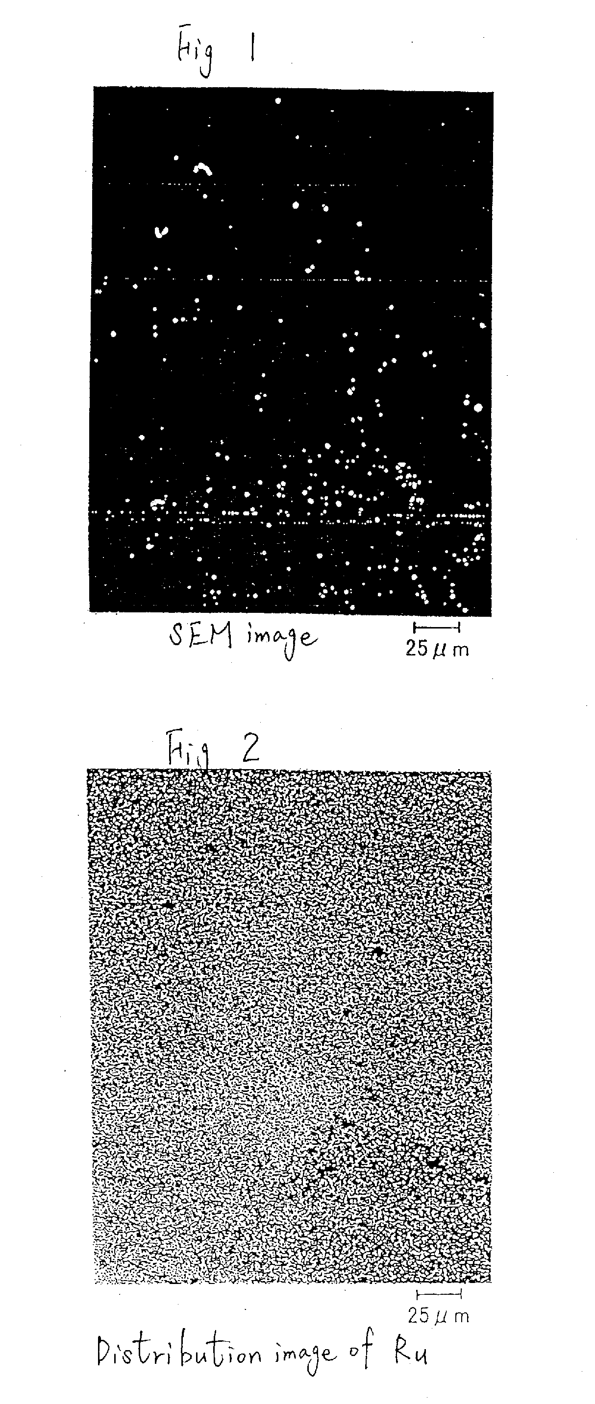
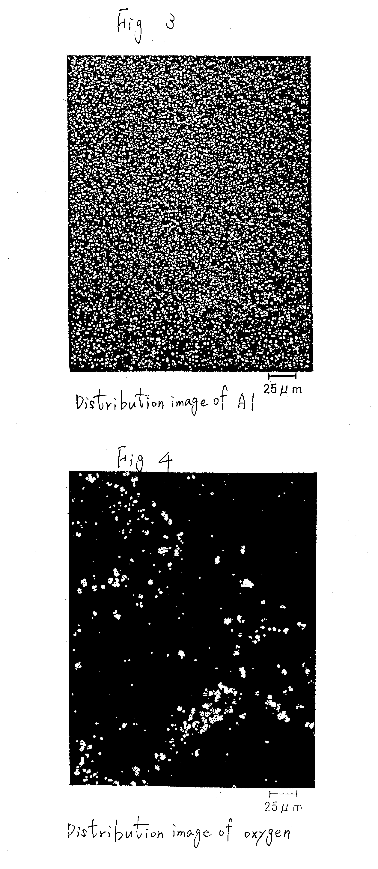
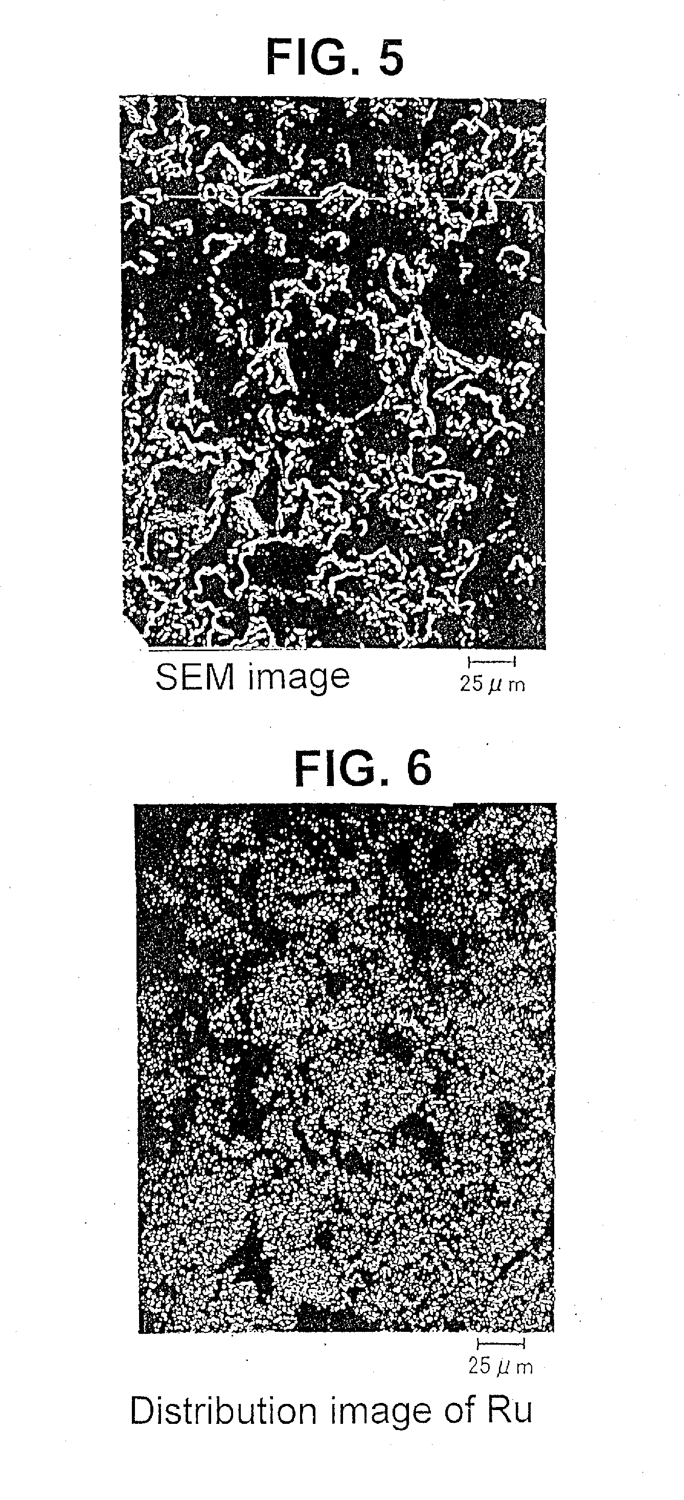
[0015] An object of the present invention is to enable the stable and low-cost manufacture of an AlRu sputtering target having an even texture and capable of significantly reducing oxygen, and to prevent or suppress the generation of particles and improve the yield ratio of deposition goods.
[0017] In order to achieve the foregoing object, as a result of intense study, the present inventors discovered that the oxygen content can be reduced, generation of particles can be prevented or suppressed, and the yield ratio of manufacture can be significantly improved by improving the manufacturing process and sintering process of powder.

Problems solved by technology

In a conventional AlRu sputtering target, there is a particular problem in that the target material is not even, and that it contains a high content of oxygen.
When employing this kind of target, there are problems in that numerous particles will be generated upon forming the sputtering film, unevenness of the film will further generate a defective deposition product, and the yield ratio will decrease.
As the usage conditions of the AlRu sputtering target, Al—50 at % Ru is employed compositionally, but since the dissolution temperature of this composition is 2000° C. or higher, it is difficult to employ a dissolution casting product as a target from the perspective of manufacturing costs.
Accordingly, upon manufacturing an Al—50 at % Ru sintered body target, when simply employing equimolar Al and Ru powders, this will result in high oxygen content and uneven textures, thereby causing the generation of particles.
In addition, with this kind of conventional manufacturing method, there is a problem in that the oxygen content cannot be reduced from the sintered body target.

Method used


Image

  • AlRu Sputtering Target and Manufacturing Method thereof
  • AlRu Sputtering Target and Manufacturing Method thereof
  • AlRu Sputtering Target and Manufacturing Method thereof

Examples


example 1

[0039] The Al and Ru raw materials were prepared to be a 20 Kg raw material where Al 3.25 mol: Ru Imol, respectively, and this was dissolved at a high frequency (in a vacuum). The dissolution temperature was 1650° C. As a result of this high frequency vacuum dissolution, it was possible to suppress the oxygen content in the hot metal to 50 wtppm.

[0040] An ingot was obtained after dissolving and casting the above, and this was pulverized to obtain powder having as its principal component an Al13Ru4 intermetallic compound. Moreover, the obtained Al13Ru4 intermetallic compound was brittle and could be pulverized easily, and powder having an average particle size of 75μm was obtained as a result thereof.

[0041] Ru powder having the same particle size as the powder having as its principal component Al13Ru4 intermetallic compound was mixed thereto, and this mixed powder was filled in a graphite dice for sintering. The amount of Ru powder to be mixed was made to be the ultimately obtained...

example 2

[0044] The Al and Ru raw materials were prepared to be a 20 Kg raw material where Al 3.25 mol: Ru imol, respectively, and this was dissolved at a high frequency (in a vacuum). The dissolution temperature was 1650° C. As a result of this high frequency vacuum dissolution, it was possible to suppress the oxygen content in the hot metal to 50 wtppm.

[0045] An ingot was obtained after dissolving and casting the above, and this was pulverized to obtain powder having as its principal component an Al13Ru4 intermetallic compound. Moreover, the obtained Al13Ru4 intermetallic compound was brittle and could be pulverized easily, and powder having an average particle size of 75 μm was obtained as a result thereof

[0046] Ru powder having the same particle size as the powder having as its principal component Al13Ru4 intermetallic compound was mixed thereto, and this mixed powder was filled in a graphite dice for sintering. The amount of Ru powder to be mixed was made to be the ultimately obtained...

example 3

[0050] The Al and Ru raw materials were prepared to be a 20 Kg raw material where Al 3.25 mol: Ru lmol, respectively, and this was dissolved at a high frequency (in a vacuum). The dissolution temperature was 1650° C. As a result of this high frequency vacuum dissolution, it was possible to suppress the oxygen content in the hot metal to 50 wtppm.

[0051] An ingot was obtained after dissolving and casting the above, and this was pulverized to obtain powder having as its principal component an Al13Ru4 intermetallic compound. Moreover, the obtained Al13Ru4 intermetallic compound was brittle and could be pulverized easily, and powder having an average particle size of 75 μm was obtained as a result thereof,

[0052] Ru powder having the same particle size as the powder having as its principal component Al13Ru4 intermetallic compound was mixed thereto, and this mixed powder was filled in a graphite dice for sintering. The amount of Ru powder to be mixed was made to be the ultimately obtaine...


PUM

PropertyMeasurementUnit
Temperatureaaaaaaaaaa
Fractionaaaaaaaaaa
Particle sizeaaaaaaaaaa

Abstract

An AlRu sputtering target that is a sintered body composed of an AlRu intermetallic compound of 95 vol.% or more is provided. It is manufactured by a stable and low-cost method that provides it with an even texture, significantly reduces oxygen, prevents or suppresses the generation of particles, and improves the yield ratio of deposition goods.

Description

CROSS REFERENCE TO RELATED APPLICATIONS [0001] This application is a divisional of U.S. application Ser. No. 10 / 479,687, which is the National Stage of International Application No. PCT / JP03 / 05757, filed May 8, 2003, which claims the benefit under 35 USC 119 of Japanese Application No. 2002-182713, filed Jun. 24, 2002.BACKGROUND OF THE INVENTION [0002] The present invention pertains to an AlRu sputtering target, and particularly to an AlRu sputtering target favorable in forming films for hard disks, as well as the manufacturing method thereof. [0003] In recent years, in order to improve the data density of hard disks, numerous materials are being considered. Among such materials, a medium employing a multilayer film having AlRu as its constituent element (composed of an element having a sandwich structure with a magnetic layer) is known to significantly improve the recording density, and it is said that in the near future it will be possible to store 100 gigabits of data per square ...

Claims


Application Information

Patent Timeline
IPC IPC(8): C23C14/00C22C1/04C22C5/04C23C14/34
CPCC22C1/0491C23C14/3414C22C5/04C22C1/047
Inventor HISANO, AKIRA
Owner JX NIPPON MINING & METALS CO LTD
Learn More