
Re-workable metallic TIM for efficient heat exchange

a heat exchange and tim technology, applied in the direction of cooling/ventilation/heating modification, semiconductor device details, semiconductor/solid-state device details, etc., can solve the problems of relative low thermal conductivity, integrated circuits require wet surfaces, heat exchangers, etc., to reduce stress transfer and simplify the assembly process

Inactive Publication Date: 2007-08-02
COOLIGY INC
View PDF99 Cites 8 Cited by
  • Summary
  • Abstract
  • Description
  • Claims
  • Application Information

AI Technical Summary

Benefits of technology

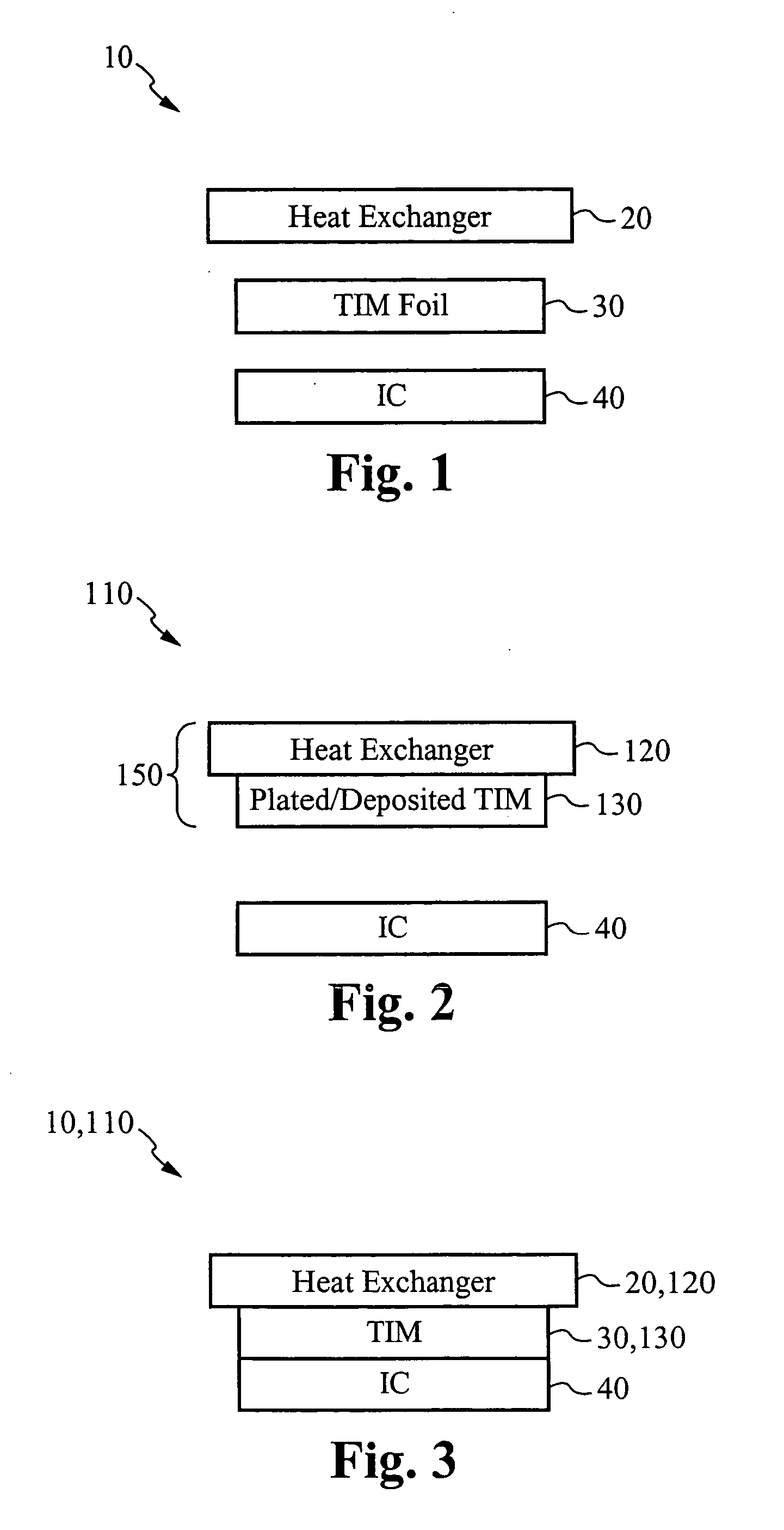
[0007] The heat exchanging system of the present invention provides many advantages. One advantage is that a metallic TIM provides efficient means of exchanging heat. A second advantage is that the assembly process is simplified and is performed at room temperature. A third advantage is that the assembly process is re-workable such that the heat exchanger, the metallic TIM foil, and the heat exchanging sub-assembly are reusable. A fourth advantage is that the compliant property of the metallic TIM provides a cushion for absorbing stresses, thereby minimizing stress transferred from the heat exchanger to the integrated circuit.

Problems solved by technology

However, polymer TIM has a relatively low thermal conductivity and thus provides a significant barrier for heat transfer from the die to the heat exchanger.
One disadvantage of using a soldering technology, such as that taught in '242, is that each of the heat exchanger, or heat spreader, and the integrated circuit requires a wet surface to join to the TIM.
Another disadvantage is that the reflow process requires heating and cooling of the TIM, and therefore the integrated circuit, which in addition to requiring an additional processing step may also damage the integrated circuit, or the surrounding sub-assembly.
Several of these steps also involve vacuum processing, which adds complexity.
Still another disadvantage is that once the reflow process is performed, the process is not re-workable, and the TIM is not reusable.

Method used


Image

  • Re-workable metallic TIM for efficient heat exchange
  • Re-workable metallic TIM for efficient heat exchange
  • Re-workable metallic TIM for efficient heat exchange

Examples


Embodiment Construction

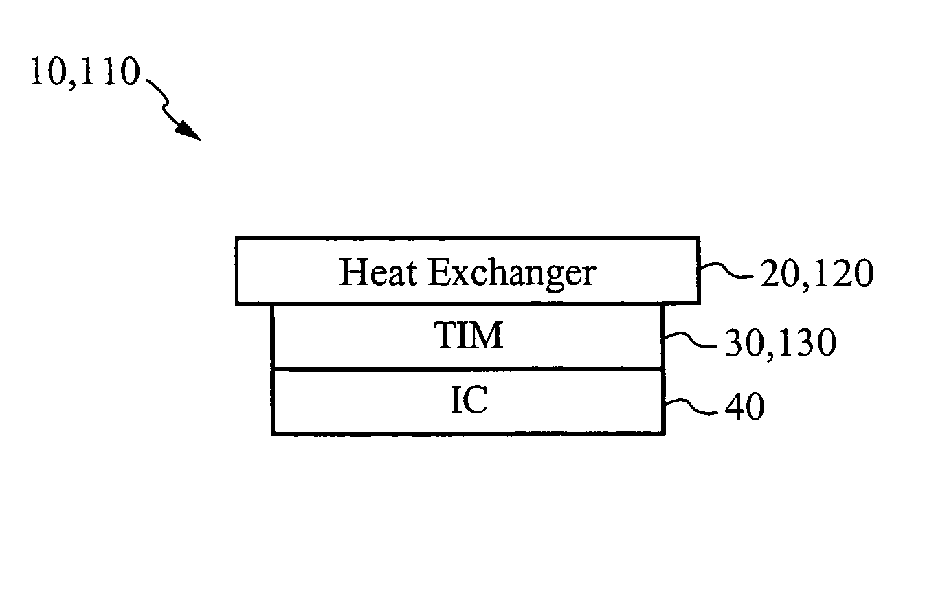
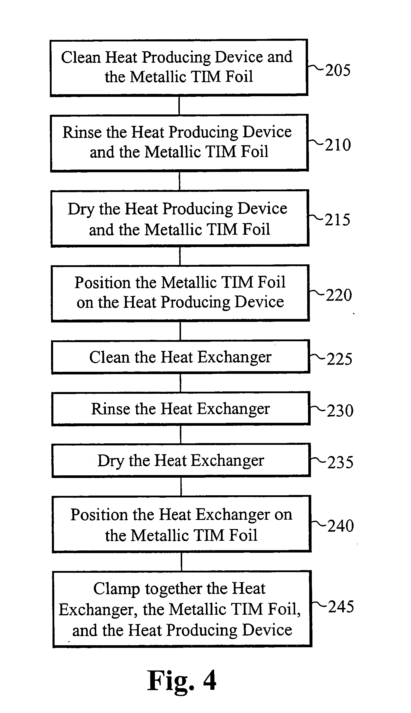
[0017]FIG. 1 illustrates components of a heat exchanging system 10 according to a first embodiment of the present invention. The components are illustrated in FIG. 1 before the heat exchanging system 10 is assembled. The heat exchanging system 10 includes a heat exchanger 20, a metallic TIM foil 30 and a heat source 40. Preferably, the heat source 40 is an integrated circuit, although the heat exchanging system 10 can be used to cool any heat generating device. The integrated circuit 40 is preferably coupled to a printed circuit board (not shown). The metallic TIM foil 30 preferably comprises indium. Indium is a relatively compliant, or soft, material. As such, the metallic TIM foil 30, when pressed into contact with the integrated circuit 40, acts as a cushion. In this manner, stress imparted to the integrated circuit 40 is minimized in at least two different ways. First, stress imparted by the weight of the metallic TIM foil 30 and the heat exchanger 20 onto the integrated circuit...


PUM


Abstract

A heat exchanging system uses a metallic TIM for efficient heat transfer between a heat source and a heat exchanger. The heat source is preferably an integrated circuit coupled to a circuit board. The metallic TIM preferably comprises indium. The metallic TIM is comprised of either a separate metallic TIM foil or as a deposited layer of metal material. The metallic TIM foil is mechanically joined to a first surface of the heat exchanger and to a first surface of the integrated circuit by applying sufficient pressure during clamping. Disassembly is accomplished by un-clamping the heat exchanger, the metallic TIM foil, and the integrated circuit from each other. Once disassembled, the heat exchanger and the metallic TIM foil are available to be used again. If the metallic TIM is deposited onto the heat exchanger, disassembly yields a heat exchanging sub-assembly that is also reusable.

Description

FIELD OF THE INVENTION [0001] The invention relates to an apparatus for cooling a heat producing device and a method of constructing thereof. In particular, the present invention relates to a re-workable metallic TIM for efficient heat exchange. BACKGROUND OF THE INVENTION [0002] Operation of an integrated circuit produces heat. As integrated circuits increase in processing power, the production of heat also increases. In current microprocessor assemblies, a heat exchanger is thermally coupled to an integrated circuit, or die, in order to remove the heat produced by the integrated circuit. The heat exchanger is typically positioned above the die. In one approach, the heat exchanger is thermally coupled to the die by means of a polymer thermal interface material (TIM), such as thermally conductive grease. However, polymer TIM has a relatively low thermal conductivity and thus provides a significant barrier for heat transfer from the die to the heat exchanger. [0003] In another approa...

Claims


Application Information

Patent Timeline
IPC IPC(8): H05K7/20
CPCH01L23/3735H01L2224/73253H01L23/473H01L23/3736
Inventor DATTA, MADHAVZHOU, PENGHOM, JAMESMUNCH, MARKMCMASTER, MARK
Owner COOLIGY INC
Learn More