
Means and a method for connecting pieces of a tube

a hollow tube and connecting method technology, applied in the direction of paper/cardboard containers, lamination, containers, etc., can solve the problems of composite sticks that are prone to breakage during normal use, heavy solid shafts, and significant warranty and service problems for suppliers, so as to minimize the peak stress transfer load

Inactive Publication Date: 2011-05-05
BOURNE ORSON +1
View PDF4 Cites 2 Cited by
  • Summary
  • Abstract
  • Description
  • Claims
  • Application Information

AI Technical Summary

Benefits of technology

The invention proposes a shaft repair solution that can mimic the performance and feel of the original shaft. It is designed to be a "do it yourself" solution and can be adjusted to players' needs. The invention includes an insert that is a hollow shaft with a central rectangular section and two tapered sections on either side. The insert fits snuggly inside the first piece of hollow tube and is designed to maintain the original kick point of the shaft.

Problems solved by technology

These solid shafts were heavy and had very little flexibility.
The major limitation of all of these designs is that all of these composite sticks are prone to breakage during normal use.
As the new shaft and stick designs often have a significant replacement cost associated with them, this can lead to significant warranty and service issues for suppliers as well as frustration on the part of consumers.
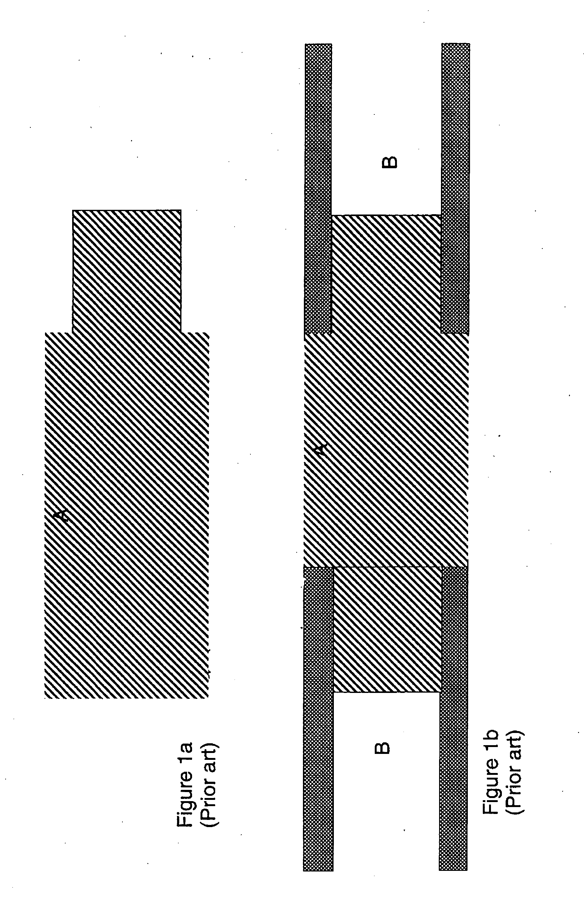
Part A has been shaped to fit into the two parts of broken shaft B. This type of repair insert has however proven to be impractical and the repaired shaft's performance was unsatisfactory.
The major reasons were weight, poor flexibility, low strength and it could not reproduce the all important “feel” (strength: weight: flexibility ratio) that was present in the original shaft.
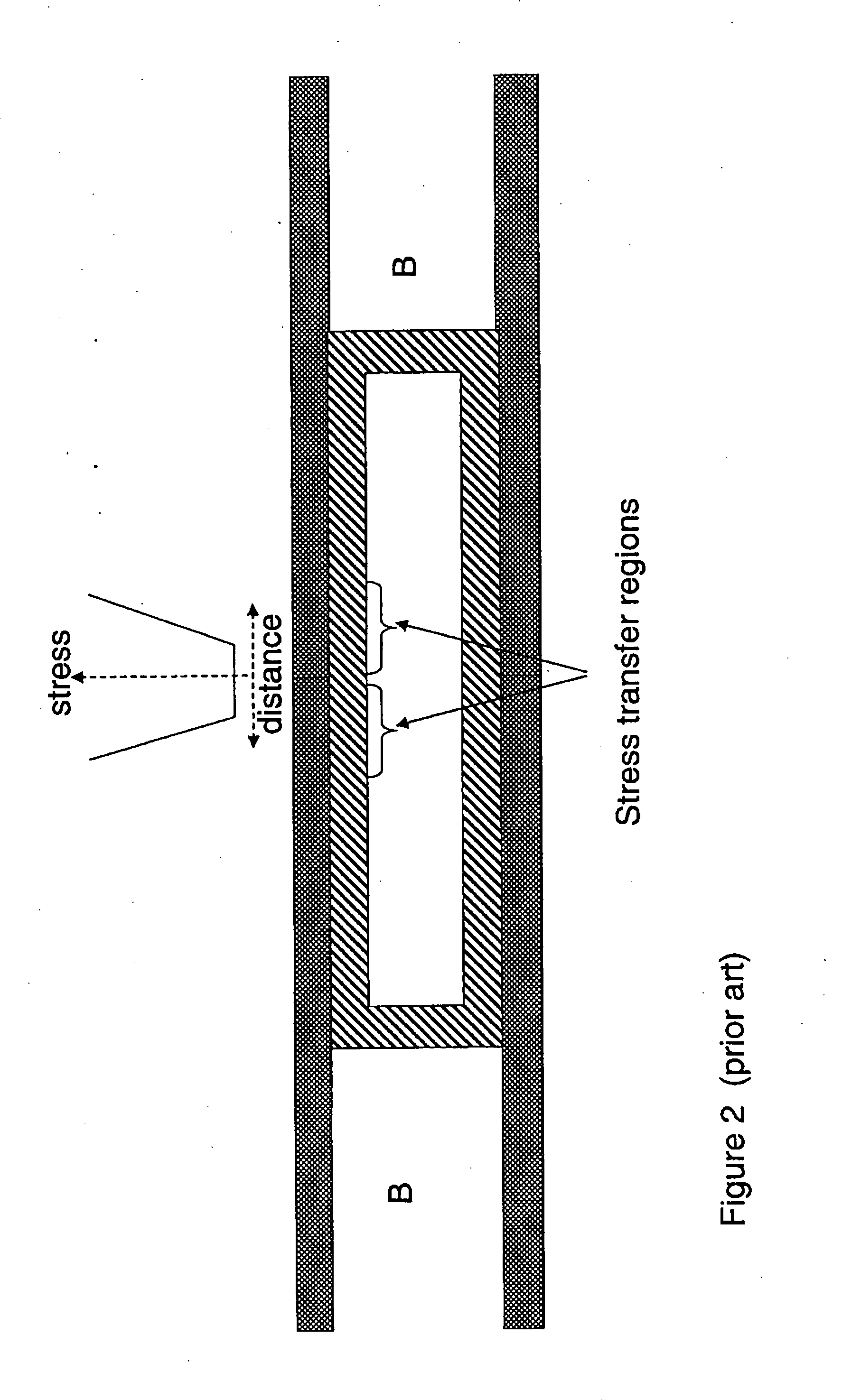
Failure at the joint interface caused by stress severely limited the viability of this repair option.
This solution is technically challenging and can only be performed by a skilled operator.
It takes up to 96 hours to complete and more importantly the feel (stench: weight; flexibility ratio) of the original shaft cannot be reproduced.

Method used


Image

  • Means and a method for connecting pieces of a tube
  • Means and a method for connecting pieces of a tube
  • Means and a method for connecting pieces of a tube

Examples


Embodiment Construction

insert being a hollow tube adapted to fit snuggly inside a first piece of hollow shaft and a second piece of hollow shaft, a bonding means, and instruction on how to install said insert to connect the first and the second hollow shafts.

BRIEF DESCRIPTION OF THE DRAWINGS

[0024]FIG. 1 (prior art) illustrates a wooden shaft extender.

[0025]FIG. 2 (prior art) illustrates a composite insert of similar cross section as the tube.

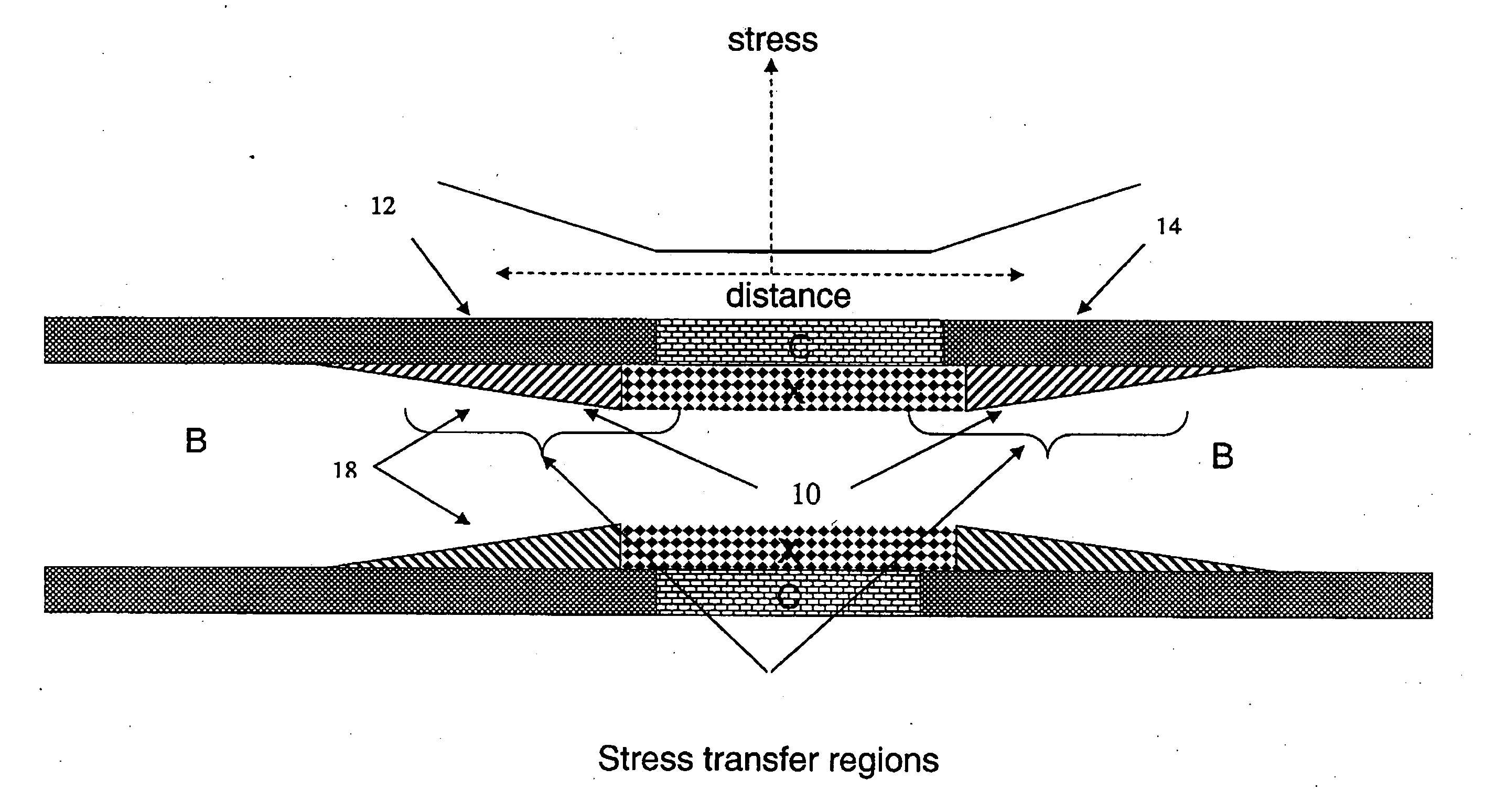
[0026]FIG. 3 illustrates one embodiment of the invention.

[0027]FIG. 4 illustrates a second embodiment of the invention.

[0028]FIG. 5 illustrates a cross section of one embodiment of the invention used in a rectangular cross section shaft.

DESCRIPTION OF PREFERRED EMBODIMENTS

[0029]FIG. 3 illustrates an insert that minimizes the peak stress transfer loading between the insert (8) and a first and a second part of a shaft (2 and 4) that it links. The insert (8) can be made of composite materials.

[0030]In a composite joint, inappropriate stress transfer at the joint interfac...


PUM

PropertyMeasurementUnit
lengthaaaaaaaaaa
lengthaaaaaaaaaa
total lengthaaaaaaaaaa

Abstract

Connecting means for connecting a first piece of hollow tube to a second piece of hollow tube. This means comprises an insert, where the insert is a hollow shaft having an external and an internal cross section. The internal cross section of said insert having a central rectangular section. The internal cross section having a first and a second tapered sections on either side of the central rectangular section tapering down from the height of the central rectangular section down to zero. The external cross section of the insert is adapted to fit snuggly inside the first piece of hollow tube and said second piece of hollow tube and the insert is adapted to minimize the peak stress transfer loading between the insert and the first and second piece of hollow tube. It also comprises a bonding means, where the bonding means adapted to secure the insert to the inside said first and second piece of hollow tube. The invention also consists in a kit. A kit which would comprise of an insert, the insert being a hollow tube adapted to fit snuggly inside a first piece of hollow shaft and a second piece of hollow shaft, a bonding means, and instruction on how to install said insert to connect the first and the second hollow shafts.

Description

[0001]This application claims the benefit of U.S. Provisional Application 60 / 800,841 filed May 17, 2006.FIELD OF THE INVENTION[0002]This invention relates to a means and a method of connecting two pieces of a hollow tube. More specifically to a composite insert adapted to connected two pieces of hollow tube such as a hollow hockey stick shaft.BACKGROUND OF THE INVENTION[0003]Over the years, advancements in material technology have lead to increase sophistication in the manufacturing and performance of hockey sticks.[0004]In the past hockey sticks were manufactured primarily of wood. The wood stick comprised a solid shaft either machined out of a single piece of wood or by sandwiching multiple layers of wood together. These solid shafts were heavy and had very little flexibility. The ability to induce flex into a stick is desirable. The energy stored in the flex generates a greater release of velocity to the puck during a slap shot or faster release during a wrist or snap shot than a...

Claims


Application Information

Patent Timeline
Patent Type & Authority Applications(United States)
IPC IPC(8): B29C73/06B29C73/08B32B1/08B82Y30/00
CPCB29C73/04Y10T428/13Y10T428/139B82Y30/00
Inventor BOURNE, ORSONSTRONG, CHARLES
Owner BOURNE ORSON
Learn More