Image recording apparatus

Inactive Publication Date: 2007-07-19
BROTHER KOGYO KK
View PDF1 Cites 7 Cited by
  • Summary
  • Abstract
  • Description
  • Claims
  • Application Information

AI Technical Summary

Benefits of technology

[0008]The carriage in Japanese Patent Application Laid-Open No. 2005-081691 (Refer to FIG. 2, FIG. 3, and FIG. 4) has the recording head on the lower surface side and an ink tank on the upper surface side. On the other hand, in Japanese Patent Application Laid-Open No. 2003-011340 (Refer to FIG. 1, FIG. 2, and FIG. 3), the reciprocating carriage is connected to the ink tank which is left at rest within the printer apparatus through an ink supply tube (an ink supply pipe) capable of being curved (having a flexibility). In this case, even if a shield plate is provided between the tape scale and the no-end belt for conveyance of the recording head, when the ink supply tube and the tape scale are arranged in proximity with each other, the curved portion of the ink supply tube scrapes against the surface of the tape scale and the ink easily adheres to the surface of the tape scale. Accordingly, the accuracy of detection of the linear encoder is easily lowered or deteriorated.
[0009]In order to solve the above-described problems, an object is to provide an image recording apparatus, which is constituted so as to make adhesion of the ink mist to the tape scale itself less and so as to be capable of reliably prevent lowering of the detection accuracy of the linear encoder by preventing contact between the tape scale and the ink supply tube.
[0011]According to the aspect, when the carriage is moving along the primary scanning direction, even if the ink supply tube is moved along with movement of the carriage, the ink supply tube is merely brought into contact with a partition wall. Thus, it does not prevent the smooth movement of ink supply tube. Then, it has an advantage such that the surface of the tape scale and the ink supply tube are not brought into contact with each other because they are blocked by a partition wall; and the detection accuracy of the linear encoder is not deteriorated (lowered) when the ink adheres to the surface of the tape scale.

Problems solved by technology

However, due to a minute ink drop injected from a recording head upon the image recording operation, an ink mist (a misty floating ink) floating within the main body of the apparatus adheres to the linear encoder, so that accuracy of detection of a scale tends to be largely lowered.
For example, in Japanese Patent Application Laid-Open No. 2005-081691 (Refer to FIG. 2, FIG. 3, and FIG. 4), since distances in height from a position of a recording head up to a tape scale and an optical sensor part are short, the ink mist easily adheres to the tape scale and the optical sensor part and the accuracy of detection of the linear encoder is easily deteriorated.
Accordingly, the accuracy of detection of the linear encoder is easily lowered or deteriorated.

Method used


Image

  • Image recording apparatus
  • Image recording apparatus
  • Image recording apparatus

Examples


Embodiment Construction

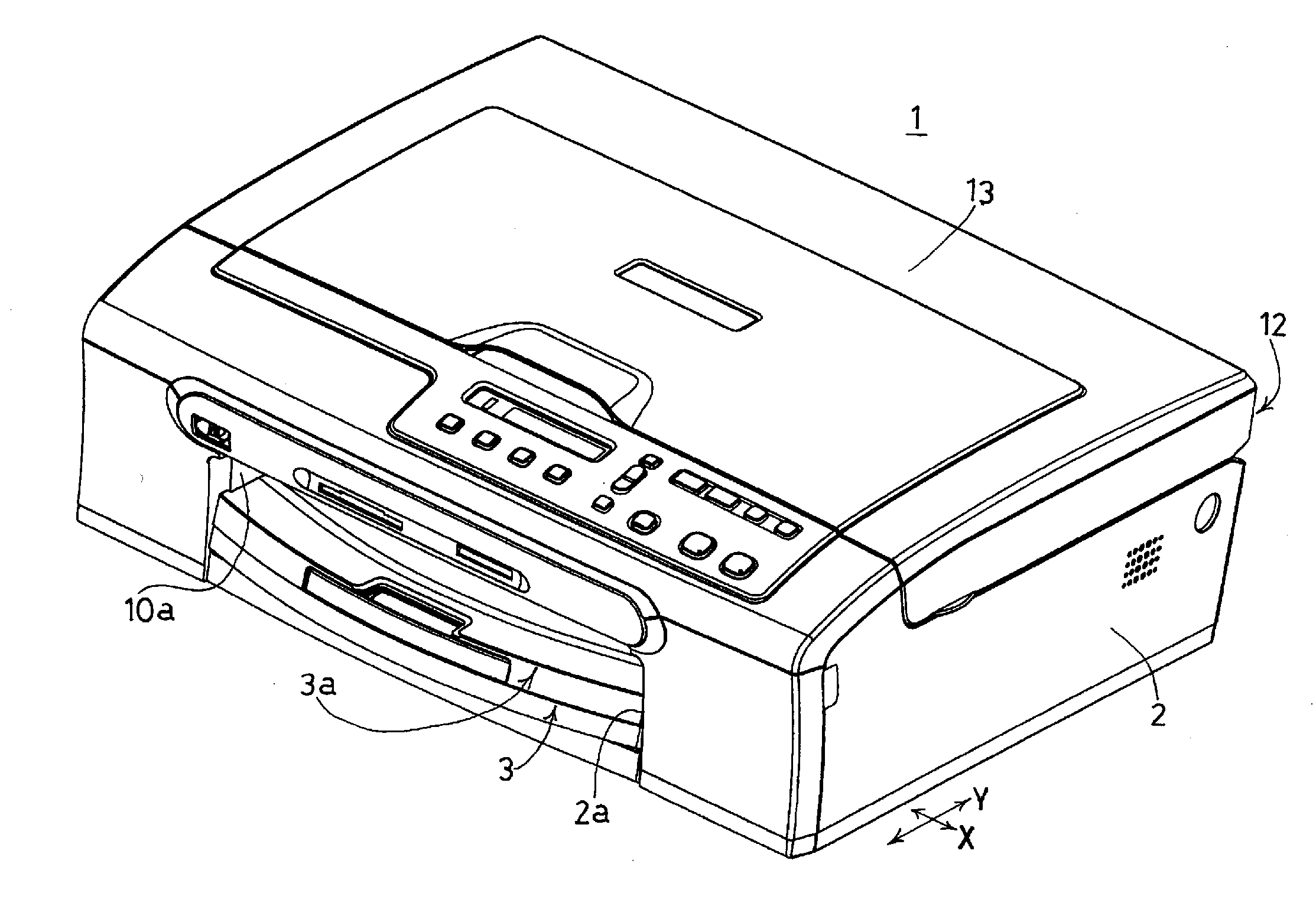
[0029]An image recording apparatus 1 according to an embodiment is an aspect of to a multi function device (MFD), which is provided with a printer function, a copy function, a scanner function, and a facsimile function. As shown in FIG. 1, on a bottom of a main body of a recording apparatus 2 made of a synthetic resin of the apparatus, a sheet feeding cassette 3 which can be inserted from an opening portion 2a on the front side (the left side in FIG. 1) of the main body of the recording apparatus 2 is arranged. Hereinafter, the side where the opening portion 2a is located is referred to as a front side or a front portion and on the basis of this, the front side, right and left sides, and a rear side of the apparatus are determined.

[0030]According to the present embodiment, a plurality of sheets P as a recording medium which is cut into, for example, into an A4 size, a letter size, a legal size, and a card size is laminated (accumulated) and stored in the sheet feeding cassette 3 so ...


PUM


Abstract

An image recording apparatus has a recording head for recording an image on a recording medium, an ink supply source for supplying an ink to the recording head through an ink tube, a carriage for mounting the recording head thereon reciprocating in a primary scanning direction, and first and second guide members for supporting the carriage thereacross and guiding reciprocating movement of the carriage. The apparatus includes a scale provided on the second guide member along the primary scanning direction, a detector provided on the carriage for detecting a reciprocating position of the carriage in corporation with the scale, and a partition disposed in the vicinity of the scale for separating at least a part of the ink tube from the scale.

Description

CROSS-REFERENCE OF RELATED APPLICATION[0001]This non-provisional application claims priority under 35 U.S.C. §119(a) on Patent Application No. 2006-008303 in Japan on Jan. 17, 2006, the entire contents of which are hereby incorporated by reference.BACKGROUND[0002]The present invention relates to an image recording apparatus, which is provided with a linear encoder for detecting a position and a moving rate of a carriage in the case of recording an image while reciprocating a carriage having a recording head of an ink jet type mounted thereon in a direction orthogonal to a conveying direction of a recording medium.[0003]As a conventional image recording apparatus, for example as disclosed in Japanese Patent Application Laid-Open No. H05-077514 (Refer to FIG. 1 and FIG. 3) and Japanese Patent Application Laid-Open No. 2005-081691 (Refer to FIG. 2, FIG. 3, and FIG. 4), a linear scale of on optical system linear encoder extending along a primary scanning direction in order to detect a p...

Claims


Application Information

Patent Timeline
IPC IPC(8): B41J2/015
CPCB41J19/207B41J2/175
Inventor SAMOTO, KENJI
Owner BROTHER KOGYO KK
Why Eureka
Try Eureka