
Substrate supporting apparatus and manufacturing method therefor

a technology of supporting apparatus and substrate, which is applied in the direction of mechanical apparatus, chemical vapor deposition coating, coating, etc., can solve the problems of structural solidity problem of conventional substrate supporting apparatus, brittle breakage of spacer members, and reducing the quality of semiconductors, so as to prevent slipping or breaking of spacer members

Active Publication Date: 2007-07-12
NHK SPRING CO LTD
View PDF7 Cites 304 Cited by
  • Summary
  • Abstract
  • Description
  • Claims
  • Application Information

AI Technical Summary

Benefits of technology

[0010] An object of the present invention is to provide a substrate supporting apparatus, capable of preventing slipping-off or breakage of spacer members and also supporting a substrate in a cleaner state.
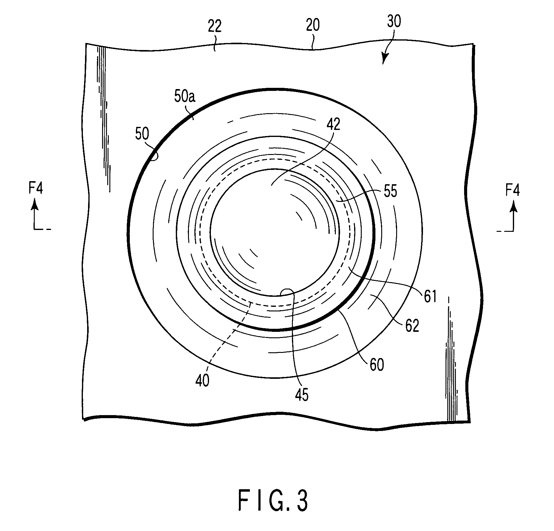
[0012] According to this arrangement, there is no possibility of the spacer member slipping out of the pit, and the spacer member can be prevented from being cracked owing to a difference in thermal expansion coefficient or the like. If any particulate dust or the like that causes contamination exists on the plate member, the groove and a bump near the bending portion can restrain it from being transferred from the upper surface of the plate member onto the spacer member. Thus, a substrate can be kept cleaner when it is supported.

Problems solved by technology

If any particulate dust, a contributor to contamination, exists on the plate member and adheres to the reverse side of the wafer, it lowers the quality of semiconductors.
Accordingly, an excessive stress is generated in the spacer members and may possibly break the spacer members that are brittle.
Thus, the conventional substrate supporting apparatus has a problem in structural solidity to resist a heat cycle or the like.

Method used


Image

  • Substrate supporting apparatus and manufacturing method therefor
  • Substrate supporting apparatus and manufacturing method therefor
  • Substrate supporting apparatus and manufacturing method therefor

Examples


Embodiment Construction

[0027] Substrate supporting apparatuses according to embodiments of the present invention will now be described with reference to FIGS. 1 to 9.

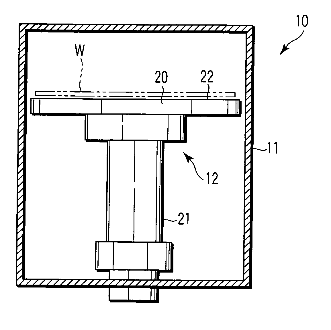
[0028]FIG. 1 shows a wafer processor 10 that is used in, for example, semiconductor manufacturing processes. The wafer processor 10 is used in processes such as chemical vapor deposition (CVD), plasma vapor deposition (PVD), etching, etc. The processor 10 comprises a sealed case 11 and a substrate supporting apparatus 12 that is arranged in the case 11.

[0029] The substrate supporting apparatus 12 includes a disc-shaped plate member 20 of a metal, such as an aluminum alloy, a post member 21 that supports the plate member 20 from the underside, and the like. The plate member 20 contains a heater unit (not shown). The heater unit heats the plate member 20 to a predetermined temperature. A substrate W, such as a wafer as an example of a supported object (workpiece), is placed on an upper surface 22 of the plate member 20.

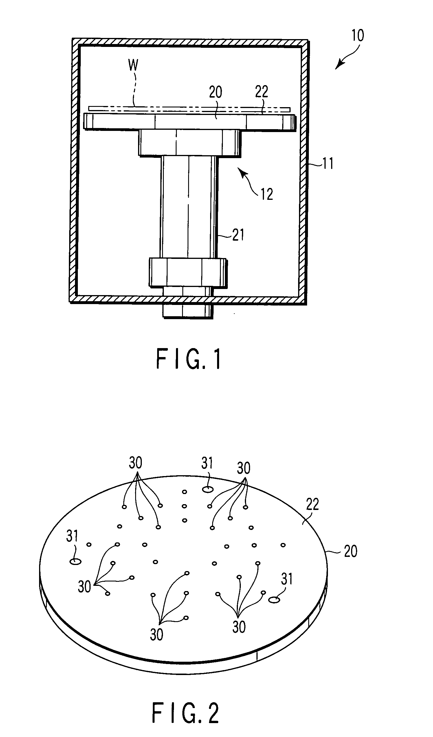
[0030]FIG. 2 is a pers...


PUM

PropertyMeasurementUnit
Circumferenceaaaaaaaaaa

Abstract

A substrate supporting apparatus includes a plate member of an aluminum alloy having a flat upper surface, bottomed pits formed in the plate member, and spacer members held in the pits, individually. The spacer members are sapphire spheres. The diameter of each spacer member is a little smaller than that of each pit. The upper end of each spacer member projects from the upper surface of the plate member. A spot facing is formed in a region that includes the open edge portion of the pit. A bending portion which is obtained by plastically deforming the open edge portion of the pit toward the spacer member is formed on a bottom surface of the spot facing. A V-shaped groove is formed behind the bending portion.

Description

CROSS-REFERENCE TO RELATED APPLICATIONS [0001] This application is based upon and claims the benefit of priority from prior Japanese Patent Application No. 2005-376558, filed Dec. 27, 2005, the entire contents of which are incorporated herein by reference. BACKGROUND OF THE INVENTION [0002] 1. Field of the Invention [0003] The present invention relates to a substrate supporting apparatus used in an apparatus for processing, for example, a semiconductor wafer or the like and a manufacturing method therefor. [0004] 2. Description of the Related Art [0005] In semiconductor manufacturing processes, a substrate supporting apparatus that has a heating function and the like is used to process a substrate, such as a wafer. The substrate supporting apparatus has a plate member for supporting the substrate. The substrate is placed on the upper surface of the plate member. [0006] If any particulate dust, a contributor to contamination, exists on the plate member and adheres to the reverse side...

Claims


Application Information

Patent Timeline
IPC IPC(8): C23C16/00H01K3/10
CPCC23C16/4581F16C29/046Y10T29/49165H01L21/68757H01L21/6875
Inventor KIDA, NAOYATACHIKAWA, TOSHIHIROFUTAKUCHIYA, JUN
Owner NHK SPRING CO LTD
Learn More