Plasma processing system

a processing system and plasma technology, applied in the field of plasma processing system, can solve the problems of plurality of sensors of the same type, uniform sensitivities, and inability to connect high-frequency signal-detecting probes to such a plasma processing system, and achieve the effect of facilitating the setting of target load impedance zl and facilitating examination

Active Publication Date: 2007-07-05
DAIHEN CORP
View PDF6 Cites 27 Cited by
  • Summary
  • Abstract
  • Description
  • Claims
  • Application Information

AI Technical Summary

Benefits of technology

[0025] The present invention has been proposed in view of the above-described situation. It is an object of the present invention to provide a high-frequency measurement unit capable of performing accurate high-frequency measurement with respect to a predetermined frequency range by acquiring a small number of calibration coefficients. Another object of the present invention is to provide an automatic adjustment unit that automatically adjusts an adjustment position of a variable capacitor to facilitate the setting of a target load impedance ZL in a dummy load. Further, still another object of the present invention is to provide an automatic adjustment unit that facilitates the examining, in advance of the actual use of the plasma processing unit, what conditions permit the impedance matching unit to achieve impedance matching.
[0031] Preferably, the high-frequency measurement unit of the present invention may further comprise a phase detection unit that detects a phase of the high-frequency signal based on the high-frequency voltage signal detected by the voltage detection unit and the high-frequency current signal detected by the current detection unit. In this embodiment, the calibration coefficient storage unit may further store phase calibration coefficients Cdmin, Cdmax used for calibrating a phase difference θmin at the lower limit frequency fmin and a phase difference θmax at the upper limit frequency fmax to a proper phase difference θSmin and a proper phase θSmax respectively, where the phase differences are detected by the phase detection unit. The calibration coefficient calculation unit may further calculate a phase calibration coefficient Cdm for the frequency fm based on the lower limit frequency fmin, the upper limit frequency fmax, the frequency fm detected by the frequency detection unit, and the phase calibration coefficients Cdmin, Cdmax stored in the calibration coefficient storage unit. The measured value calibration unit may further calibrate a phase difference θm detected by the phase detection unit to a proper phase difference θSm, where this calibration is based on the phase calibration coefficient Cdm calculated by the calibration coefficient calculation unit.
[0034] According to the high-frequency measurement unit of the present invention, even when the frequency fm of the high-frequency signal fluctuates in a predetermined range, the calibration coefficient Cm corresponding to the frequency fm is calculated by linear interpolation based on the calibration coefficient Cmin corresponding to the lower limit frequency fmin and the calibration coefficient Cmax corresponding to the upper limit frequency fmax, both coefficients being stored in the calibration coefficient storage unit. Then, by utilizing the calibration coefficient Cm, a detected value Am such as a high-frequency voltage or current signal is adjusted to the proper value ASm. In this manner, it is possible to perform accurate measurement of a high-frequency signal in a predetermined frequency range with use of a small number of calibration coefficients.
[0036] With the above arrangements, the electrical characteristic adjustment apparatus is capable of calculating an error evaluation value, or an index indicating the error between a measured impedance of a dummy load and the target impedance, with one of e.g. two variable capacitors of the dummy load fixed while the other kept changing. Then, the electrical characteristic adjustment apparatus adjusts the variable capacitor so that the error evaluation value becomes minimal. Thereafter, the electrical characteristic adjustment apparatus switches the role of the capacitors, i.e., the variable capacitor to be fixed in capacitance and the other capacitor to be varied, and executes the above minimizing adjustment. In this manner, an appropriate impedance is set for the dummy load.
[0038] With the above arrangement in the electrical characteristic adjustment apparatus, it is possible to reduce the time required for finding the minimum of the error evaluation value.
[0040] With the above arrangement, it is possible to change the adjustment range of a variable capacitor in proportion to the previous adjustment amount of the same variable capacitor. This facilitates effective adjustment.

Problems solved by technology

Accordingly, the high-frequency signal-detecting probe cannot be connected to such a plasma processing system.
This is because a plurality of sensors of the same type presents, from a strict viewpoint, ununiform sensitivities.
During the plasma processing, however, the transition of status with time of the work or the plasma often provokes fluctuation in impedance of the plasma processing unit 30.
This naturally leads to a measurement error.
In this case, however, a huge number of calibration coefficients have to be acquired, and a much larger storage capacity has to be secured for those coefficients.
Besides, the job of acquiring such large calibration coefficient group constitutes a heavy burden in establishing the system.
However, such examination takes a significantly long time.
Therefore, although accurate adjustment positions are once examined and recorded, when the dummy load 400 is employed in a subsequent process the accurately identical impedance cannot be reproduced.
Consequently, the impedance setting, which consumes a considerable time, has to be executed immediately before each use of the plasma processing system.

Method used


Image

  • Plasma processing system
  • Plasma processing system
  • Plasma processing system

Examples


Embodiment Construction

[0068] Preferred embodiments of the present invention will be described below with reference to the accompanying drawings.

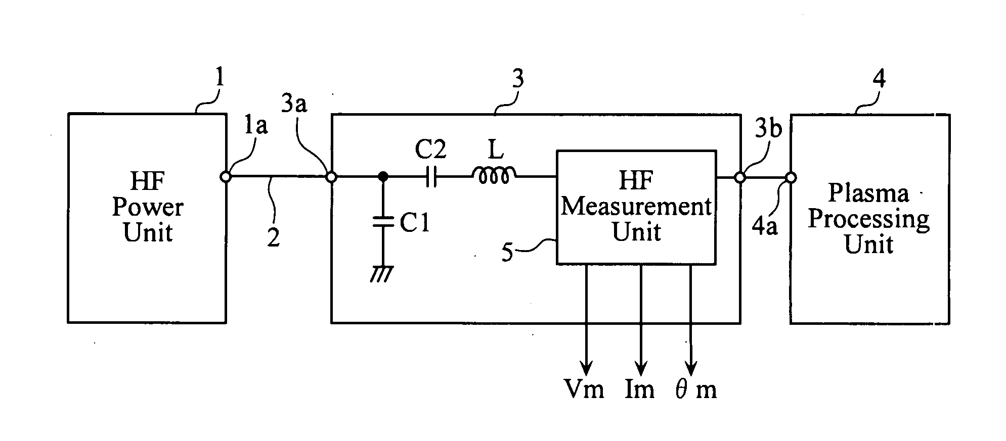
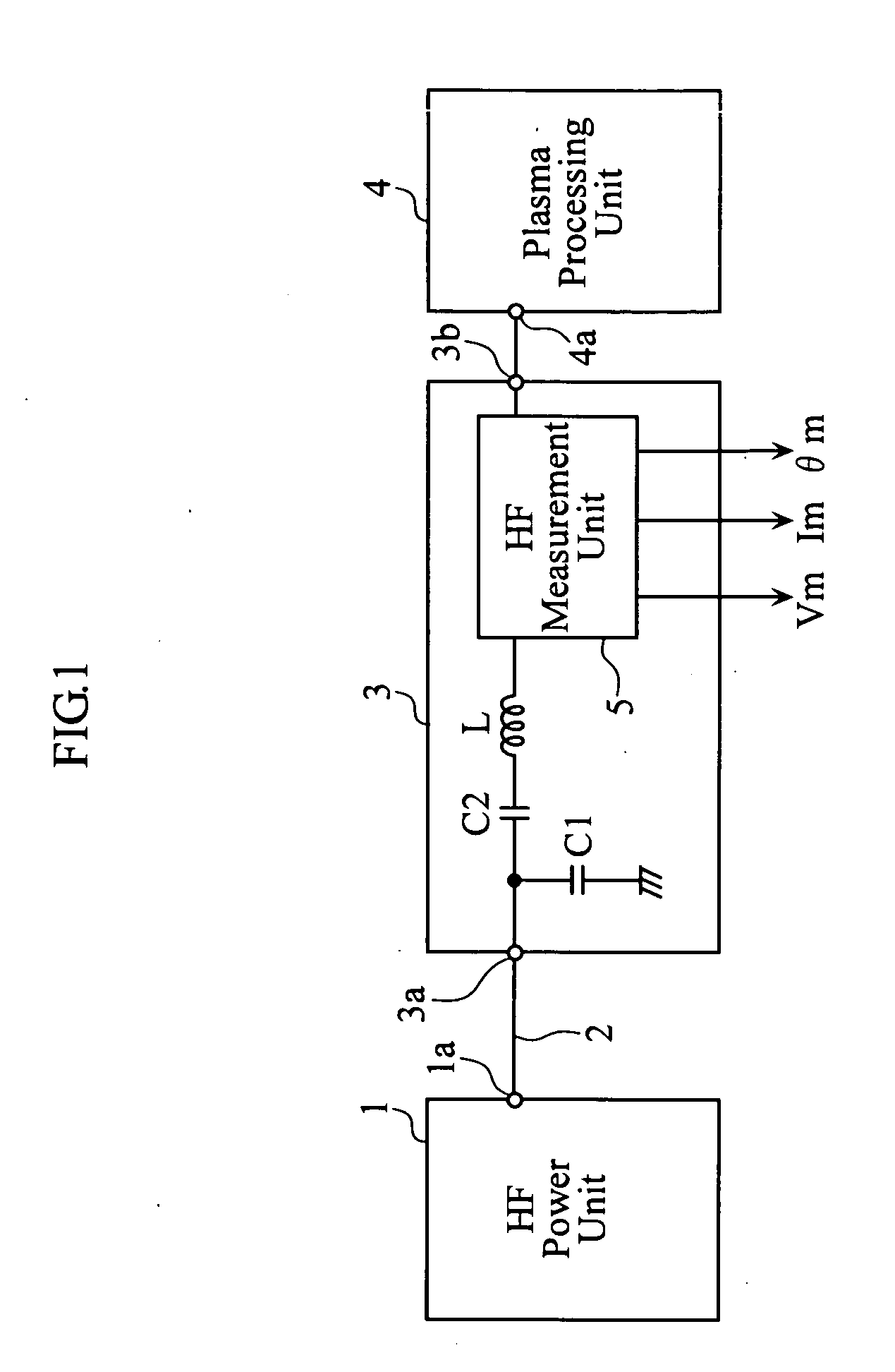
[0069]FIG. 1 is a block diagram of a plasma processing system including a high-frequency measurement unit according to the present invention. The plasma processing system is employed for executing an etching process or the like, on a work such as a semiconductor wafer or a liquid crystal substrate. The plasma processing system includes a high-frequency power unit 1, a transmission line 2, an impedance matching device 3, and a processing unit 4.

[0070] The transmission line 2 is constituted of a coaxial cable, and connects the high-frequency power source 1 and the impedance matching device 3. The impedance matching device 3 is connected to the plasma processing unit 4, which is a load.

[0071] The impedance matching device 3 serves to roughly match the impedance of the high-frequency power unit 1 with that of the plasma processing unit 4. The impedance matching de...


PUM


Abstract

A high-frequency measurement unit includes a signal detector for detecting a high-frequency signal, and a calibration coefficient storage for storing calibration coefficients Cmin and Cmax used to calibrate a value Amin detected at the lowest limit frequency fmin and a value Amax detected at the uppermost limit frequency fmax to a proper measurement value Asmin and to a proper measurement value Asmax, respectively. The high-frequency measurement unit further includes a frequency detection unit for detecting a frequency fm of the high-frequency signal, a calibration coefficient calculation unit for calculating a calibration coefficient Cm for the frequency fm, and a calibration unit for calibrating the value Am detected by the signal detector to a proper measurement value Asm by using the calibration coefficient Cm calculated by the calibration coefficient calculation unit.

Description

BACKGROUND OF THE INVENTION [0001] 1. Field of the Invention [0002] The present invention relates to a plasma processing system. In particular, the present invention relates to a high-frequency measurement unit and an electrical characteristic adjustment apparatus (for e.g. automatic impedance adjustment) that constitute a plasma processing system. [0003] 2. Description of the Related Art [0004]FIG. 7 is a block diagram of a conventional plasma processing system. The plasma processing system is employed for executing an etching process or the like on a work such as a semiconductor wafer or a liquid-crystal substrate. The plasma processing system includes a high-frequency power unit 10, an impedance matching device 20, and a plasma processing unit 30. During the plasma processing, a mismatch of impedance emerges between the high-frequency power unit 10 and the plasma processing unit 30, because of large fluctuation in impedance of the plasma processing unit 30. The impedance matching...

Claims


Application Information

Patent Timeline
IPC IPC(8): G01R35/00
CPCH01J37/321H05H1/46H01J37/32935H01J37/32174
Inventor MATOBA, HIROSHITANAKA, RYOHEIOMAE, SHUJIAMADATSU, SHIGEKI
Owner DAIHEN CORP
Why Eureka
Try Eureka