
Linear turbo equalization using despread values

a turbo equalization and despread value technology, applied in the field of communication, can solve problems such as loss of orthogonality, loss of dispersed characteristics, and achieving higher bit rates, and achieve the effect of suppressing self-interferen

Active Publication Date: 2007-06-28
TELEFON AB LM ERICSSON (PUBL)
View PDF16 Cites 110 Cited by
  • Summary
  • Abstract
  • Description
  • Claims
  • Application Information

AI Technical Summary

Benefits of technology

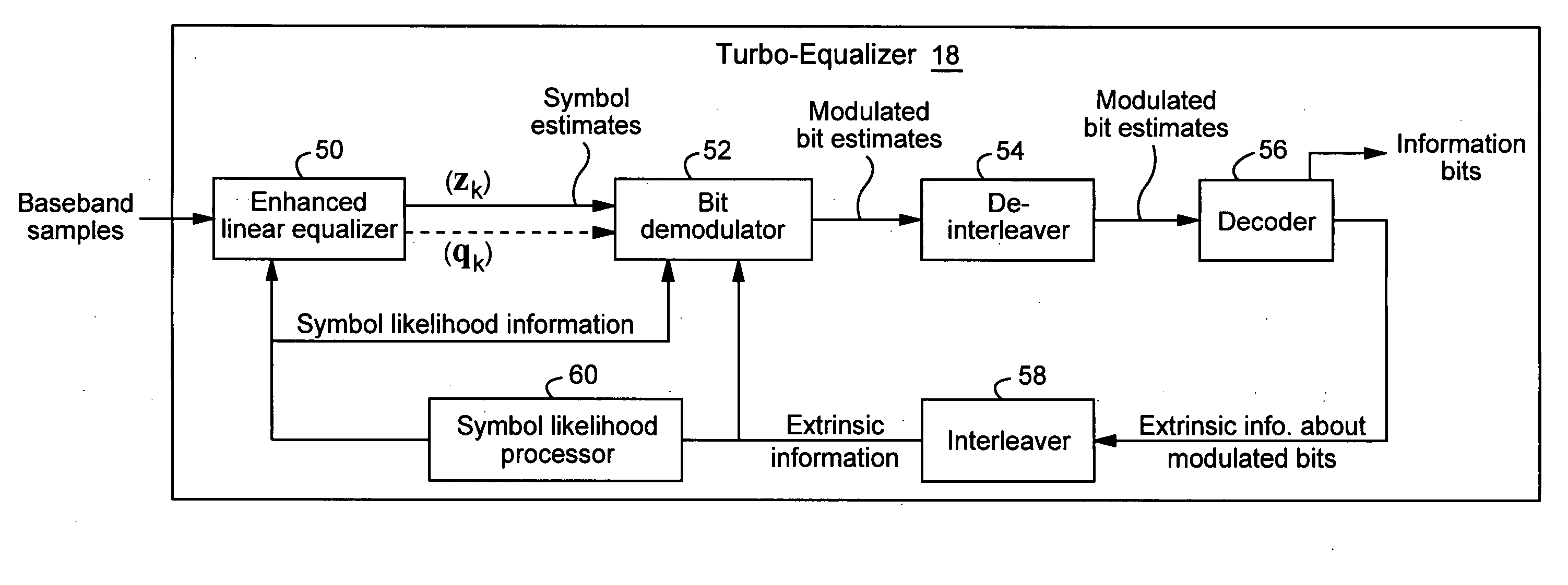
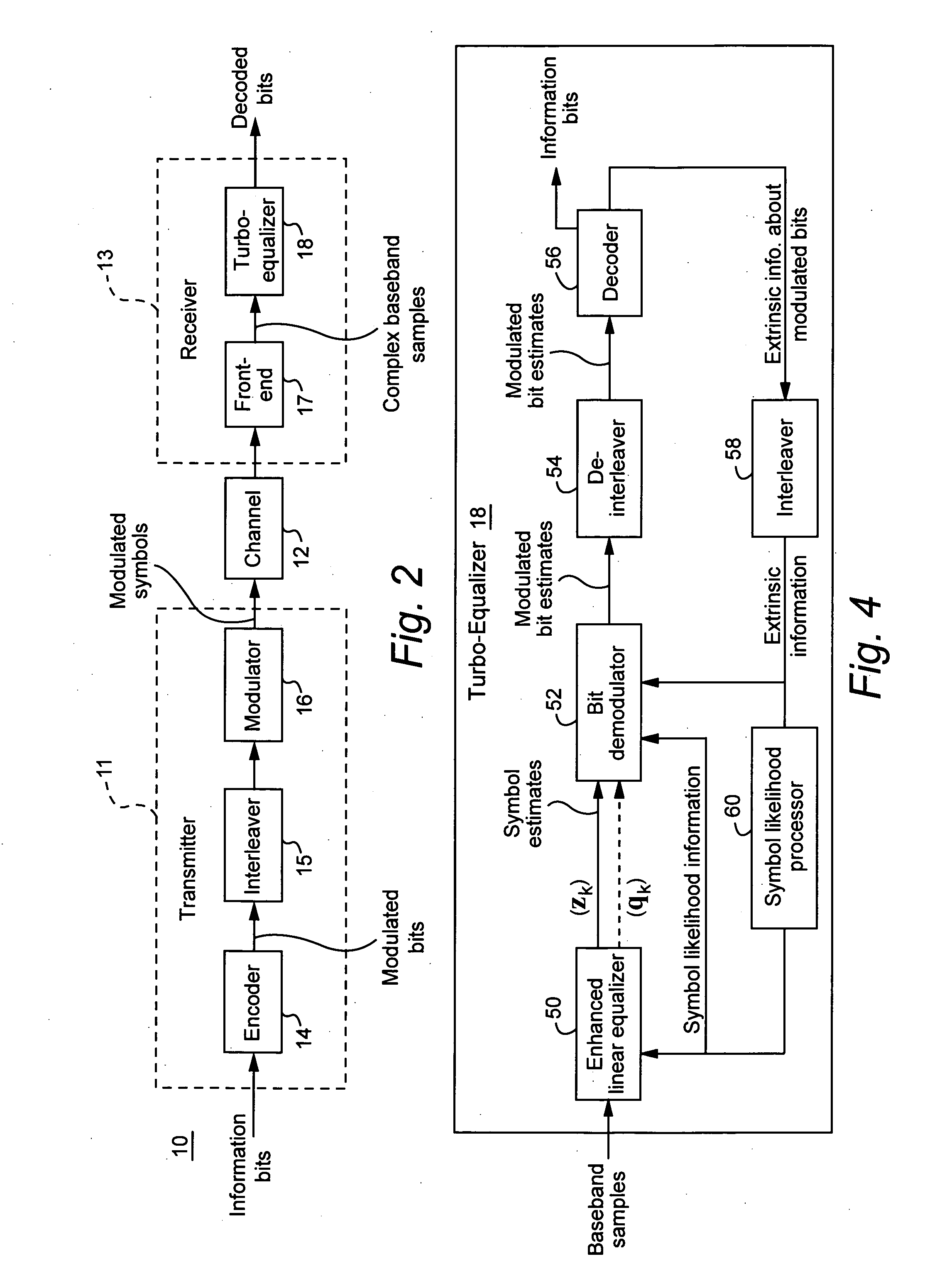
[0010] A linear turbo-equalizer for use in a CDMA receiver equalizes a despread received signal (rather than the spread received signal) to suppress self-interference resulting from coupling between transmitted symbols. This approach fits very well into existing CDMA radio receivers that employ traditional Rake receiver architectures and offers an alternative to chip equalization. In an example implementation, a linear equalizer based on a generalized-Rake (G-Rake) receiver design uses decoder fe

Problems solved by technology

A major obstacle to achieving higher bit rates relates to the dispersive characteristics of a radio channel.
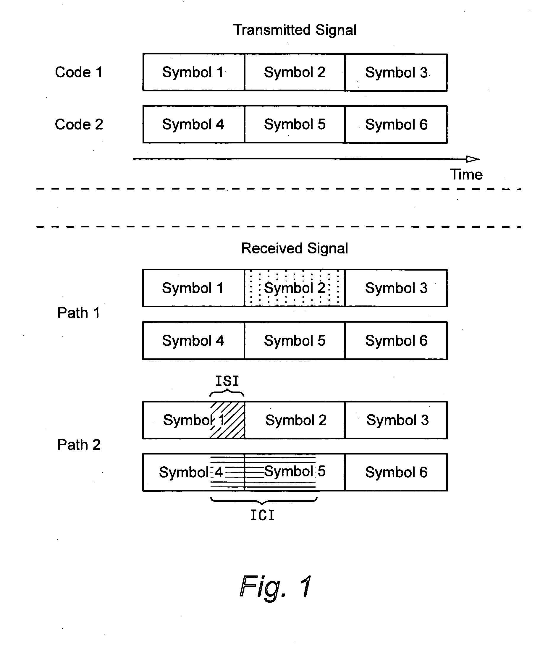
If the channel is dispersive, self-interference results primarily due to loss of orthogonality between the multi-code signals.
Another form of self-interference is interference from successive symbols on the same code.
Higher-order modulation is particularly sensitive to self-interference.
At high rates, dispersion leads to significant self-interference.
The main limitation with linear equalization is the limited amount of interference suppression.
But this enhances noise and other forms of interference.
Thus, this trade-off prevents full restoration of orthogonality.
The drawback is much higher complexity relative to linear equalization.
But modem symbol detection is not always accurate.
Thus, interference cancellation can actually worsen the situation when symbol detection errors are made.
Also, such an approach does not utilize forward error correction (FEC) coding structure to obtain reliable modem symbol estimates.
Again, the problem is complexity.
A drawback with chip equalization is that it is complicated; it is easier to equalize the despread signal.

Method used


Image

  • Linear turbo equalization using despread values
  • Linear turbo equalization using despread values
  • Linear turbo equalization using despread values

Examples


Embodiment Construction

[0029] In the following description, for purposes of explanation and non-limitation, specific details are set forth, such as particular nodes, functional entities, techniques, protocols, standards, etc. in order to provide an understanding of the described technology. It will be apparent to one skilled in the art that other embodiments may be practiced apart from the specific details disclosed below. In other instances, detailed descriptions of well-known methods, devices, techniques, etc. are omitted so as not to obscure the description with unnecessary detail. Individual function blocks are shown in the figures. Those skilled in the art will appreciate that the functions of those blocks may be implemented using individual hardware circuits, using software programs and data in conjunction with a suitably programmed microprocessor or general purpose computer, using applications specific integrated circuitry (ASIC), field programmable gate arrays, one or more digital signal processor...


PUM


Abstract

A linear turbo-equalizer for use in a CDMA receiver equalizes a despread received signal (rather than the spread received signal) to suppress self-interference resulting from coupling between transmitted symbols. In an example implementation, a linear equalizer based on a generalized-Rake (G-Rake) receiver design uses decoder feedback in forming Rake combining weights as well as in forming a self-interference estimate removed from the equalizer signal provided to the decoder. Preferably, turbo de-coding is also performed. In that case, each turbo-decoder component preferably executes one pass before feeding back information to the equalizer. This ensures that the turbo-decoder does not prematurely lock onto an incorrect code word before feeding back extrinsic information to the equalizer.

Description

TECHNICAL FIELD [0001] The technical field relates to communications, and more particularly, to demodulation in a direct sequence-code division multiple access (DS-CDMA) communications system. BACKGROUND [0002] Third generation cellular communications employ wideband CDMA (WCDMA). CDMA is a method for transmitting simultaneous signals over a shared portion of the spectrum. CDMA spreads the signal over the full bandwidth of the CDMA frequency band using a spreading code that, because it is orthogonal to all the other spreading codes used, allows each modulated bit stream to be distinguished (decoded) at the receiver from all of the other signals and noise. The rate of the spreading signal is known as the “chip rate,” as each bit in the spreading signal is called a “chip”, e.g., one bit from the modulated bit stream is spread into 128 chips, giving the receiver an enormous amount of data it can average to determine the value of one bit. [0003] A Rake receiver structure is commonly use...

Claims


Application Information

Patent Timeline
IPC IPC(8): H04B1/00H03D1/00H04B1/10
CPCH03M13/2957H03M13/6331H04B1/712H04B2201/709727H04L1/0048H04L1/005H04L25/03063
Inventor BOTTOMLEY, GREGORY E.CHENG, JUNG-FU
Owner TELEFON AB LM ERICSSON (PUBL)
Learn More