Color image sensor unit and image reading apparatus using the sensor unit and control method therefor
a color image sensor and image reading technology, applied in the direction of optical radiation measurement, instruments, spectrometry/spectrophotometry/monochromators, etc., can solve the problems of lowering the s/n ratio of the b component signal, and difficulty in performing the superimposition of the rgb signal by the delay processing in the unit of one line, so as to prevent color misalignment of the image signal
- Summary
- Abstract
- Description
- Claims
- Application Information
AI Technical Summary
Benefits of technology
Problems solved by technology
Method used
Image
Examples
embodiment 1
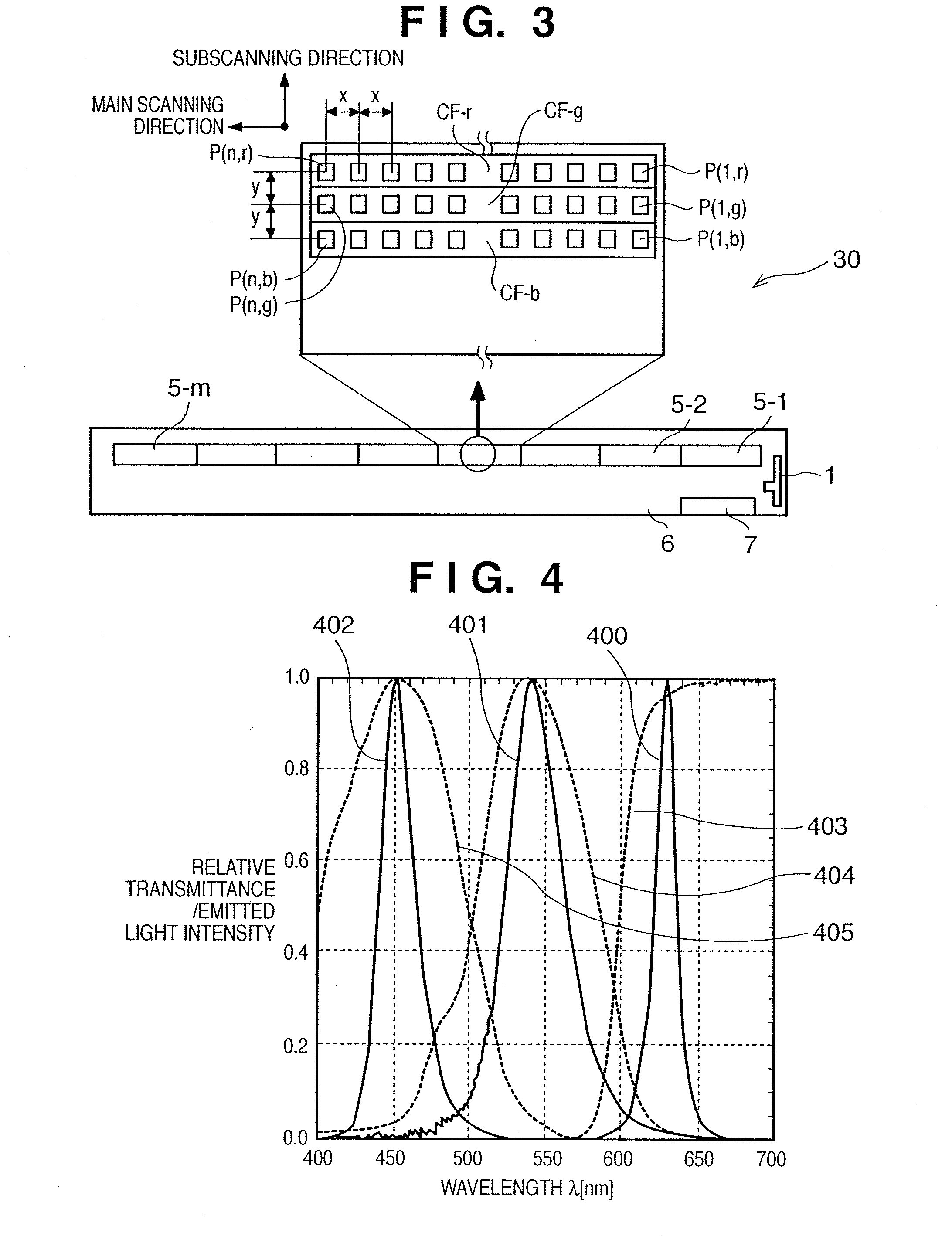
[0075]FIG. 1 is a block diagram showing a constitution of a color contact image sensor (CIS) unit according to an embodiment of the present invention. Note that the CIS unit according to the present embodiment comprises at least a light source 1, a light guide member 2 for illuminating in the width direction of an original with light from the light source 1, and a sensor array 5 for detecting reflected light from the original.
[0076] In FIG. 1, the light source 1 is a light source for illuminating the original 9, and light emitting elements 1-r, 1-g and 1-b for respectively emitting light having wavelengths of primary three colors (RGB) are mounted to the light source 1. The light emitted from the light source 1 is introduced into the inside of the light guide member 2 arranged in the width direction of the original, and guided in the perpendicular direction (main scanning direction) in FIG. 1, so as to irradiate as linear light flux from a light emitting section provided for the li...
embodiment 2
[0103] Next, an embodiment 2 according to the present invention is described with reference to FIG. 8.
[0104] A constitution of a color sensor according to the present embodiment 2 is the same as that of the above described embodiment 1, but is different in the method for driving each of three light emitting elements 1-r, 1-g and 1-b which constitute the light source, that is, different in the light emission start timing. The three light emitting elements 1-r, 1-g and 1-b have an independent drive circuit, respectively. The lighting start timing and the lighting period of the three light emitting elements are independently controlled, during one operating cycle TW, by drive signals φLR, φLG and φLB which correspond to the three light emitting elements, respectively. For example, in the example shown in FIG. 8, the drive signal φLR of the light emitting element 1-r is turned on after a period TNR from the rise time of the signal SP, and is set at a high level during a period TWR. Thi...
embodiment 3
[0117] By using the driving method of the light source according to the above described embodiment 2, the interval y between the pixel arrays in the subscanning direction can be arbitrarily set independently of the interval x between the pixels. In the case where the interval y between the pixel arrays is set smaller than the interval x between the pixels, the inter-line delay processing for correcting the color misalignment can be eliminated, even when the reading operation is performed on the basis of the basic resolution of sensors which is determined by the interval x between the pixels.
[0118]FIG. 9D is a figure showing an operation timing when the resolution in the main scanning direction is equal to the resolution in the subscanning direction. For example, a case where the interval y between the pixel arrays is set to ½ of the interval x between the pixels is considered. Also in this case, the delay periods TNR, TNG and TNB which determine the lighting start timings of the re...
PUM
 Abstract
Description
Claims
Application Information
 - R&D
- Intellectual Property
- Life Sciences
- Materials
- Tech Scout
- Unparalleled Data Quality
- Higher Quality Content
- 60% Fewer Hallucinations
Browse by: Latest US Patents, China's latest patents, Technical Efficacy Thesaurus, Application Domain, Technology Topic, Popular Technical Reports.
© 2025 PatSnap. All rights reserved.Legal|Privacy policy|Modern Slavery Act Transparency Statement|Sitemap|About US| Contact US: help@patsnap.com


