Low power consumption lock for appliance latch
a low-power consumption, latch technology, applied in the direction of mechanical equipment, carpet fasteners, cleaning equipment, etc., can solve the problems of inability to provide rapid locking and unlocking
- Summary
- Abstract
- Description
- Claims
- Application Information
AI Technical Summary
Benefits of technology
Problems solved by technology
Method used
Image
Examples
first embodiment
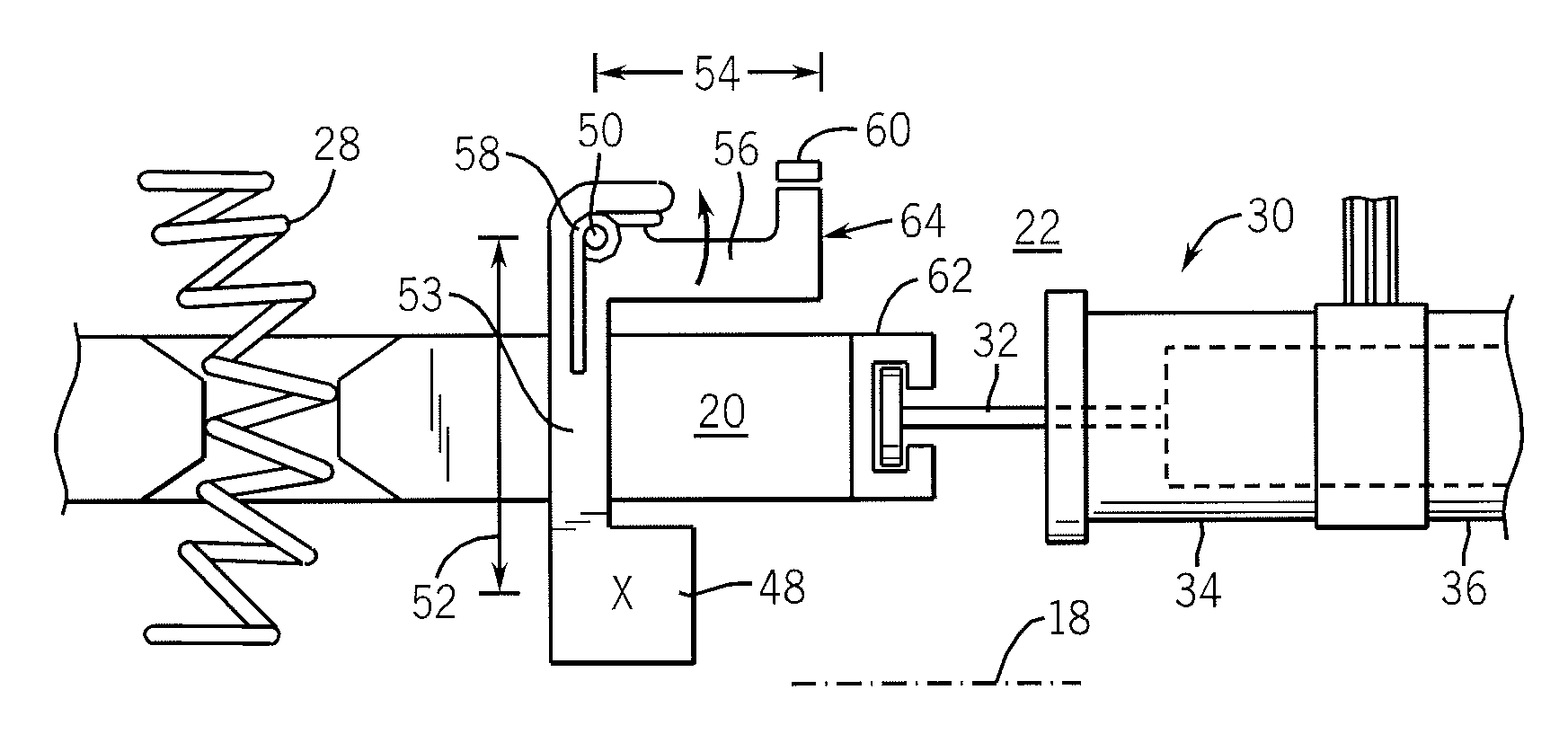
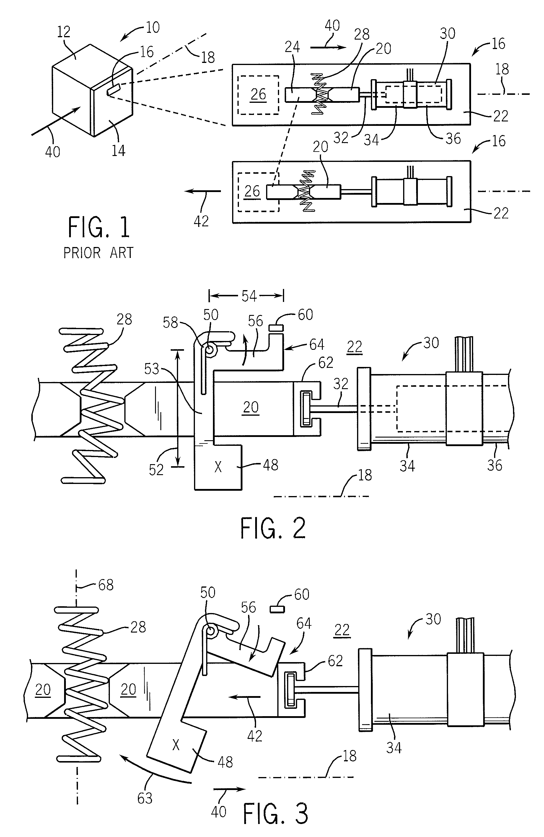
[0041] Referring now to FIG. 2, the slide 20 may rest in an unlocked state before application of any accelerative forces. In the invention, a weight 48 is positioned near the slide 20 and held by an arm 53 pivoted about a pivot point 50 so that the weight 48 may move generally in a swinging radius 52 along axis 18. A lever 56 is attached to the arm 53 joining the weight 48 to the pivot point 50 at a radius 54, and, in the rest state, extending along axis 18 adjacent to the slide 20. A torsion spring 58 biases the lever 56 in a counterclockwise direction (as shown) so that one end of the lever 56 abuts a stop 60 on a lock housing preventing further motion of the lever 56 in the counterclockwise direction. The end of the lever 56 provides a blocking surface 64 adjacent to an attachment tower 62 extending upward from the slide 20 to receive one end of the core 32 of the solenoid 30.
[0042] Referring now to FIG. 3, an acceleration 40 on the housing may apply an acceleration force on the ...
third embodiment
[0049] Referring now to FIG. 7, in a third embodiment, the effective accelerative force 42 on slide 20 may be counteracted through the use of a compensator weight 90 pivoting about a pivot point 92 adjacent to the slide 20 so that the compensator weight 90 may rotate generally along axis 18. Compensator weight 90 connects to the pivot point 92 by means of a short lever arm 94 and then continues past the pivot point 92 in a second lever arm 96 to a point over the center of the slide 20. There, the end of the second lever arm 96 engages an upstanding peg 98 attached to the slide 20. The engagement of the second lever arm 96 and the peg 98 is by means of a slotted fork connection 100 allowing relative lateral movement between the two.
[0050] During a shock causing accelerative force 42 on the slide 20, a corresponding accelerative force 42′ will act on the compensator weight 90 biasing the compensator weight 90 in a clockwise direction about pivot point 92. This, in turn, causes the for...
PUM
 Abstract
Description
Claims
Application Information
 - R&D
- Intellectual Property
- Life Sciences
- Materials
- Tech Scout
- Unparalleled Data Quality
- Higher Quality Content
- 60% Fewer Hallucinations
Browse by: Latest US Patents, China's latest patents, Technical Efficacy Thesaurus, Application Domain, Technology Topic, Popular Technical Reports.
© 2025 PatSnap. All rights reserved.Legal|Privacy policy|Modern Slavery Act Transparency Statement|Sitemap|About US| Contact US: help@patsnap.com


