System for manufacturing an inlay panel using a laser

a technology of laser manufacturing and inlay panel, which is applied in the manufacture of cable/conductor, electrical apparatus, insulation conductor/cable, etc., can solve the problems of high labor intensity, high degree of artisan skill, and significant difficulties in the art and industry of creating inlay panel, and achieve the effect of precise accuracy and mass production capability

Inactive Publication Date: 2007-06-28
RATCLIFFE BLAKE EDWARD
View PDF1 Cites 6 Cited by
  • Summary
  • Abstract
  • Description
  • Claims
  • Application Information

AI Technical Summary

Benefits of technology

The present invention is a method of making inlaid panels using a laser cutting technique to create one or many voided images in a background panel into which one or many inlay elements of various material composition can be inserted. The process is economical and time-saving, and the resulting inlaid panels have a unique appearance and can be used in various furniture and decorative objects. The technical effects of this invention include the ability to create intricate inlay panels with precise accuracy and mass production capabilities, as well as the ability to incorporate inlay elements into larger furniture designs.

Problems solved by technology

However, while inlays themselves vary widely, there are significant difficulties in the art and industry of creating inlay panels.
One such difficulty is that the industry is labor intensive and requires a high degree of skill from the artisan.
Consequently, the resulting product is correspondingly expensive.
In addition, cutting both the positive and negative images required by an inlay is tedious.
This known system, however, falls short of efficiently controlling the design accuracy and work efficiency.
However, router based systems are limited in the quality of the detail that can be cut.
Moreover, the design tolerances, which are of particular importance in the corners of the design, are limited by the diameter of the router's cutting head.
Generally, the cutting head must be of sufficiently diameter to withstand the cutting of many boards, and therefore delicate and detailed patterns are not achievable.
Thus, the inlay designs are limited to only single-plane surfaces.
Generally, the inlay can only be flush, as inlays in raised relief or recessed relief are not achievable.
However, this method is based on a saw cut method and can only be used to create a raised relief inlay.
Furthermore, none of the prior art arrangements and methods are suitable for mass scale, repeatable operation using CNC technology.
A significant drawback to this is that color, which is required to make the inlay stand out, must be impregnated in the material being inlayed.
The only way to avoid this problem requires a time-consuming and expensive use of masking tape to isolate each inlay element from its neighboring elements and then subjecting the product to spot finishing.
All too often, however, even with such precautions the colors will often bleed past the boundaries blocked by the masking tape and ruin the effect of the inlay.
This known technique, however, suffers from significant disadvantages, including that the surface sheet cannot adequately be secured to the substrate.
Thus, over time, humidity causes warpage, cracking, and detachment.
In addition, this known technique only allows thin sheets of laminate to used as the material that is revealed through the laser cut design in the surface panel.

Method used


Image

  • System for manufacturing an inlay panel using a laser
  • System for manufacturing an inlay panel using a laser
  • System for manufacturing an inlay panel using a laser

Examples


Embodiment Construction

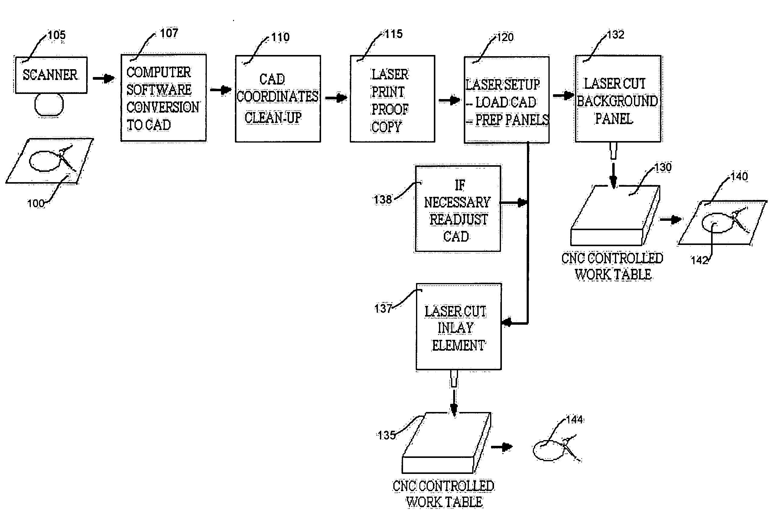
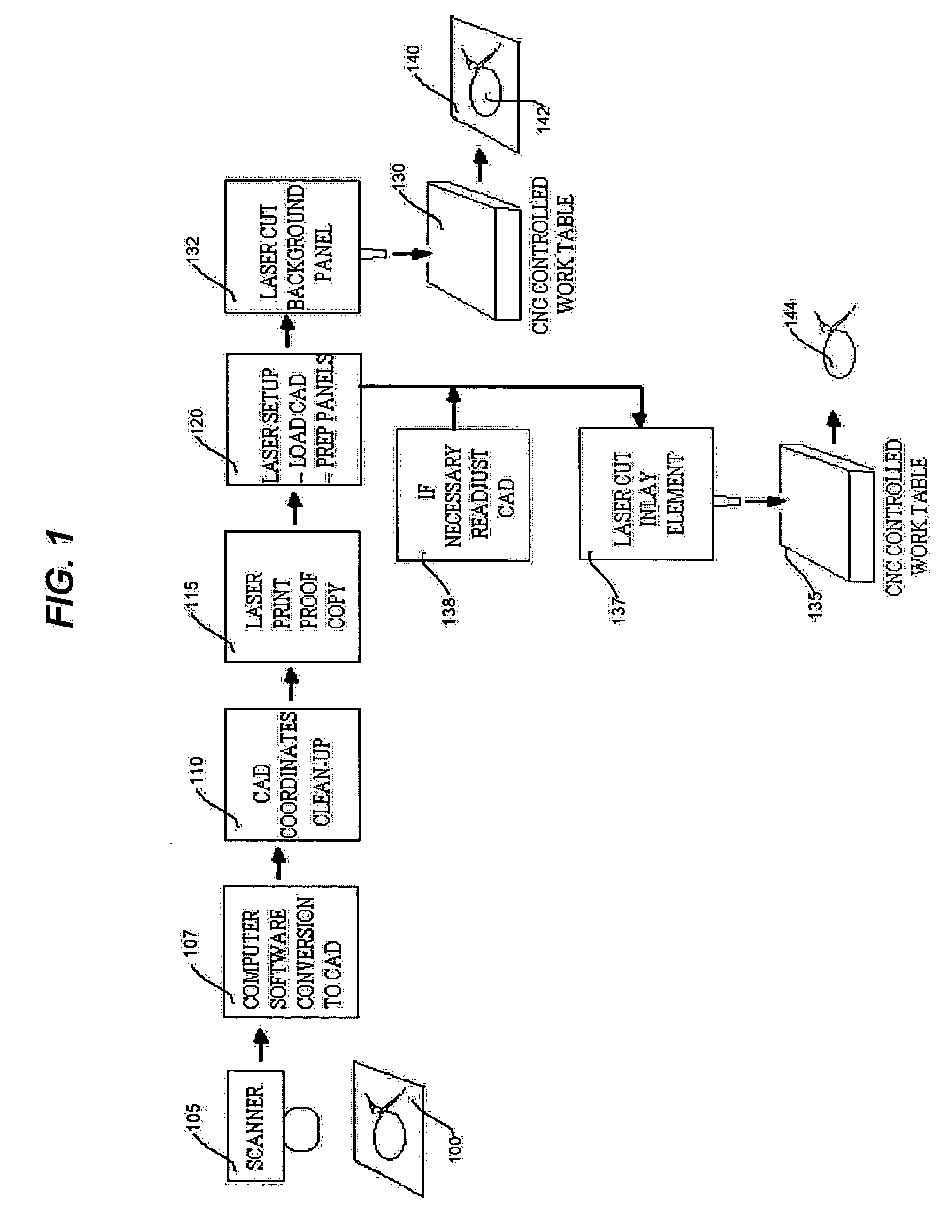
[0053]FIG. 1 is a simplified function block and schematic representation that illustrates a laser cutting process for an inlay in accordance with the principles of the invention. As shown in this figure, there is first provided an art master 100 that is provided by a designer (not shown). It is assumed that at this stage of commencement of manufacture the designer has already specified the greater context for the ultimate design of the panel within the furniture or decorative object (whether it be signage, shelf panel, door, etc.). As will be seen in connection with FIG. 2, the article to be manufactured by this illustrative process, is a shelf unit. In addition, this disclosure of a specific illustrative embodiment of the invention will focus on the cutting of a wood veneer, illustratively on a medium density fiberboard (“MDF”) core as the frame panel, and high pressure plastic laminate (“HPPL”) as the inlay element panel.

[0054] Art master 100 may be a hand or mechanically drawn r...


PUM

PropertyMeasurementUnit
pressureaaaaaaaaaa
hardnessaaaaaaaaaa
diameteraaaaaaaaaa

Abstract

A method for manufacturing a laser-cut, inlayed panel uses a computerized laser-cutting technique that includes the steps of: providing an art master rendering that is desired to constitute a decorative design for the inlaid panel; scanning electronically the art master to form an art master data file; transferring the art master data file to a CAD software system to form an art master CAD file having machine code coordinates; coordinating a laser beam to cut-through a first background panel and create negative image voids on the inlaid panel; driving a CNC laser cutting machine in response to the machine code coordinates; second coordinating a laser beam to cut through a second panel for forming positive images that become inlay elements; bonding the first background panel and the second panel for forming a composite panel; placing the inlay element in appropriate voided spaces on the background panel and bonded to the substrate; finishing the composite panel; finishing the inlay elements. The finished composite panel with affixed inlay elements is incorporated into an overall furniture or decorative object. The process may be applied to articles where the surface is curved or arcuate.

Description

RELATIONSHIP TO OTHER APPLICATION [0001] This application claims the benefit of U.S. Provisional Application No. 60 / 297,850 filed Jun. 13, 2001, and is a continuation of U.S. patent application Ser. No. 10 / 171,166 filed on Jun. 16, 2002.BACKGROUND OF THE INVENTION [0002] 1. Field of the Invention [0003] This invention relates generally to systems for manufacturing panels, and more particularly, to a system for fabricating decorative panels having intricate decorative designs inlaid therein using a laser. [0004] 2. Description of the Related Art [0005] Inlays have been incorporated into the construction of furniture and the decorative arts for centuries. Typical inlay applications vary widely and encompass many different materials and methods—from stone plaque with an embedded metal design, to table tops constructed with die-cut veneer of differing wood species assembled jig-saw puzzle style and bonded to a substrate. However, while inlays themselves vary widely, there are significan...

Claims


Application Information

Patent Timeline
Patent Type & Authority Applications(United States)
IPC IPC(8): H01B13/26
CPCB44C1/26
Inventor RATCLIFFE, BLAKE EDWARD
Owner RATCLIFFE BLAKE EDWARD
Why Eureka
Try Eureka