
Fuel cell apparatus and associated method

a fuel cell and apparatus technology, applied in the direction of cell components, electrochemical generators, cell component details, etc., can solve the problems of air electrode degradation during charging process, system efficiency suffers, air electrode material compromises

Inactive Publication Date: 2007-06-21
GENERAL ELECTRIC CO
View PDF4 Cites 22 Cited by
  • Summary
  • Abstract
  • Description
  • Claims
  • Application Information

AI Technical Summary

Benefits of technology

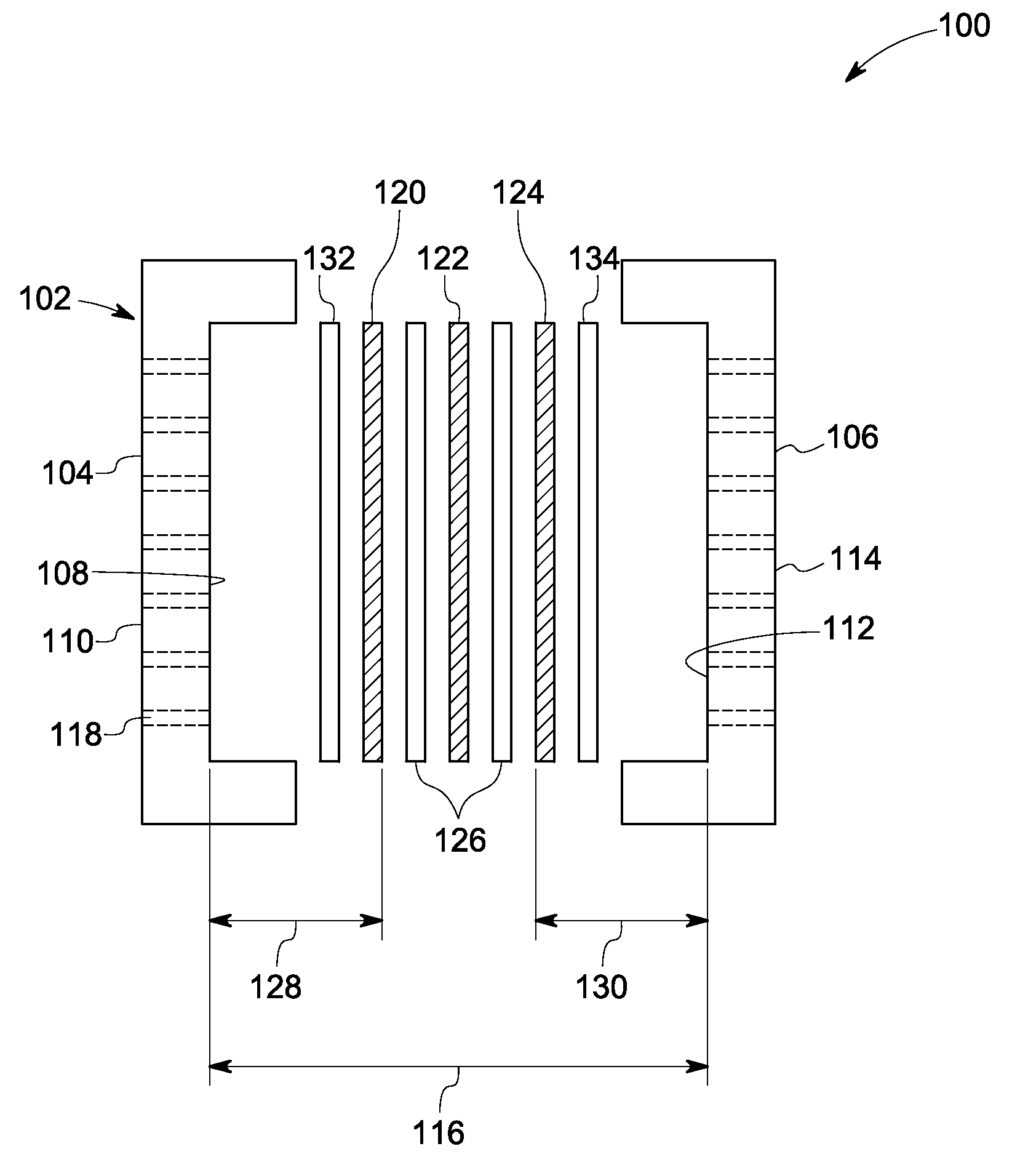
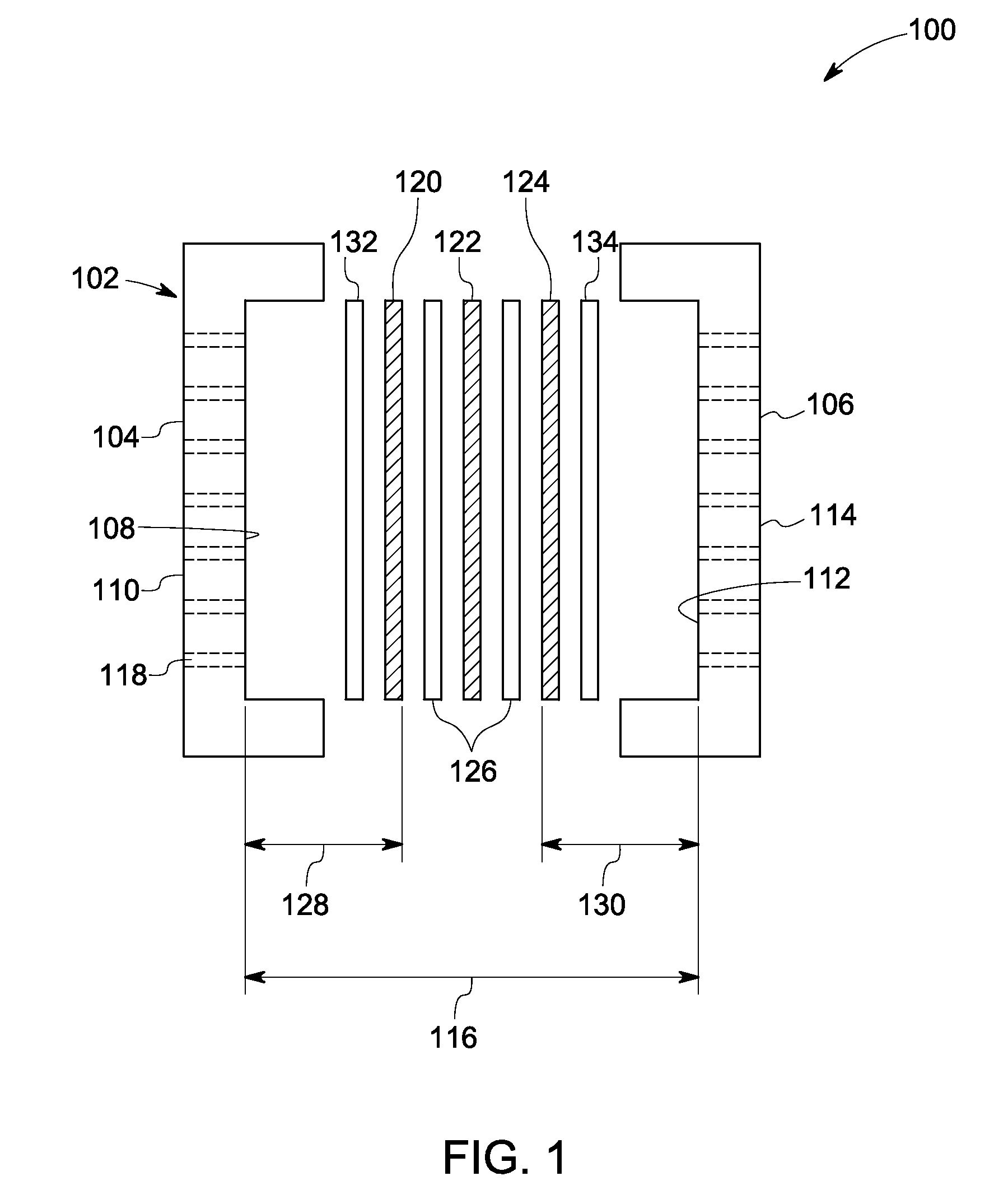
[0009] An apparatus is provided in one embodiment. The apparatus includes a housing having walls. The walls of the housing each have an inner surface and an outer surface. Each wall may include apertures extending from the inner surface to the outer surface. The inner surfaces of the walls define a volume. The volume includes an electrode. The electrode is a supercapacitor electrode. The volume further includes a water-controlling separator disposed between the inner surface of the housing and the electrode. The water-controlling separator can block a flow of liquid from the electrode through the apertures to the ambient environment while allowing oxidant to flow from the ambient environment through the apertures to the electrode.

Problems solved by technology

Fuel cell vehicles may operate on hydrogen stored onboard the vehicles, and may produce little or no conventional undesirable by-products.
However, in such a dual functional electrochemical system, where electrochemical system behaves as fuel cell in discharging process and as electrolysis cell in charging process, the air electrode may degrade quickly during charging process.
The system efficiency may suffer by the compromise of the air electrode materials for both oxygen reduction and water oxidization.
The cells may have limited specific power and energy efficiency for some applications, such as in the automotive industry.
In addition, conventional cells may suffer from water loss and oxygen evolution during charge process.

Method used


Image

  • Fuel cell apparatus and associated method
  • Fuel cell apparatus and associated method
  • Fuel cell apparatus and associated method

Examples


Embodiment Construction

[0013] The invention includes embodiments that relate to a fuel cell. The invention includes embodiments that relate to a method of using the fuel cell.

[0014] Approximating language, as used herein throughout the specification and claims, may be applied to modify any quantitative representation that could permissibly vary without resulting in a change in the basic function to which it may be about related. Accordingly, a value modified by a term such as “about” is not limited to the precise value specified. In some instances, the approximating language may correspond to the precision of an instrument for measuring the value.

[0015] According to one embodiment, an apparatus is provided. The apparatus includes a housing having one or more walls. The housing may be made of a metal, an alloy, a polymer or a refractory material. The housing wall can be of different shapes and sizes. In one embodiment, the housing may be polygonal in shape. As used herein, polygonal housing includes squa...


PUM


Abstract

An apparatus including a housing having walls is provided. The walls of the housing each have inner surfaces and outer surfaces. The walls may include apertures extending from the inner surface to the outer surface. The inner surfaces of the walls define a volume. The volume includes an electrode. The volume further includes a water-controlling separator disposed between the inner surface of the housing and the electrode. The water-controlling separator can block a flow of liquid from the electrode through the apertures to the ambient environment while allowing oxidant to flow from the ambient environment through the apertures to the electrode.

Description

TECHNICAL FIELD [0001] The invention includes embodiments that relate to an apparatus including a fuel cell. The invention includes embodiments that relate to a method of using the fuel cell. DISCUSSION OF RELATED ART [0002] An electrochemical cell may convert the chemical energy of a fuel directly into electricity without any intermediate thermal or mechanical processes. Energy may be released when a fuel reacts chemically with oxygen in the air. A fuel cell may convert hydrogen and oxygen into water. The conversion reaction occurs electrochemically and the energy may be released as a combination of electrical energy and heat. The electrical energy can do useful work directly, while the heat may be dispersed. [0003] Fuel cell vehicles may operate on hydrogen stored onboard the vehicles, and may produce little or no conventional undesirable by-products. Neither conventional pollutants nor green house gases may be emitted. The byproducts may include water and heat. Systems that rely ...

Claims


Application Information

Patent Timeline
IPC IPC(8): H01M8/04H01M4/96H01M8/06H01M4/90
CPCH01G9/08H01G9/155H01M8/04119H01M8/04216H01M8/18H01M12/005H01M12/06Y02E60/13Y02E60/50H01G11/48H01G11/46H01G11/20H01G11/78H01G11/08H01G11/52H01G11/28H01G11/32
Inventor YANG, HAIWEI, CHANGHUANG, QUNJIANLIU, JINGHUAXIONG, RIHUACAI, JUNWANG, SHENGXIAN
Owner GENERAL ELECTRIC CO
Learn More