
Device for positioning a workpiece to be cut and a method of using the same

a technology for positioning workpieces and workpieces, applied in the direction of metal sawing devices, manufacturing tools, metal sawing apparatuses, etc., can solve the problems of material waste, non-skilled people not being able to operate accurately without being confused,

Inactive Publication Date: 2007-06-21
NANJING CHERVON IND
View PDF7 Cites 8 Cited by
  • Summary
  • Abstract
  • Description
  • Claims
  • Application Information

AI Technical Summary

Benefits of technology

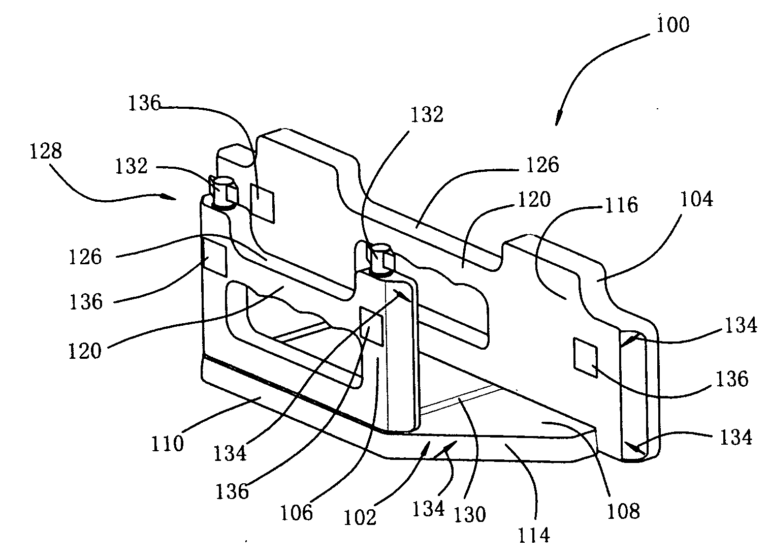
[0015] One object of the invention is to provide a device for stabilizing a workpiece, especially for stabilizing a crown molding as mentioned hereinabove, so as to assist in an accurate cutting of joint surfaces for an outside- or inside-corner joint.
[0017] Since the distance between the first supporting surface and the second supporting surface is adjustable to fit different widths of the workpieces, various workpieces can be fixed therein. To obtain a joint surface of a crown molding, merely lean the crown molding against one of the supporting surfaces, and turn the turntable of the miter saw to a required miter angle, then the saw blade may cut the molding vertically, without having to be beveled. In addition, as the first supporting surface is substantially equal to said second supporting surface in height, the workpiece may lean against either of the supporting surfaces. Furthermore, as the first side edge of the base plate is substantially parallel to the second one of the base plate, either the first side edge or the second side edge may abut the fence of the miter saw. Consequently, it is possible to perform the cutting of the four types of the joint surfaces on one side of the saw blade, thereby facilitating a left or right hand operation of an operator. These advantages will be more apparent upon consideration of the following detailed description.
[0018] A second object of the present invention is to provide a device for stabilizing a workpiece, which enables an operator to cut required joint surfaces more simply and quickly. For this purpose there are four pairs of markings on the first supporting wall, the second supporting wall and the base plate for guiding how the workpiece should be positioned for cutting. The four pairs of markings are shown in different forms, so as to be distinct from each other. Labels are provided adjacent to the oblique side edges for indicating cutting results achievable when the workpiece being oriented according to the said four pairs of markings. Consequently, an operator can position the workpiece quickly with error rate being mostly minimized.
[0031] The using method makes it possible that the cutting of four types of the joint surfaces can be performed on one side of the saw blade, thereby facilitating a left or right hand operation of an operator.

Problems solved by technology

It is thus not so easy for a non-skilled person to operate accurately without being confused.
Therefore it's all-too-easy to accidentally make cuts at the wrong settings, and end up with joints that don't mate correctly, which also results in material wasting.

Method used


Image

  • Device for positioning a workpiece to be cut and a method of using the same
  • Device for positioning a workpiece to be cut and a method of using the same
  • Device for positioning a workpiece to be cut and a method of using the same

Examples


Embodiment Construction

[0045] As shown in FIGS. 6 and 7, the stabilizing device 100 comprises a base plate 102, a first supporting wall 104 and a second supporting wall 106. The base plate 102 has a base plane 108, a first side edge 110 and a second side edge 112 which are opposite to and parallel to each other, and two oblique side edges 114. The first supporting wall 104 stands close to the first side edge 110, with two ends thereof preferably located within the oblique side edges 114 of the base plate, and the first supporting wall 104 having a first supporting surface 116 substantially perpendicular to the base plane 108. The second supporting wall 106 stands close to the second side edge 112 of the base plate 102, and has a second supporting surface 118 substantially perpendicular to the base plane 108 and parallel to the first supporting surface 116. Two ends of the second supporting wall 106 are preferably located within the oblique side edges 114 of the base plate. With such a configuration, the s...


PUM

PropertyMeasurementUnit
Angleaaaaaaaaaa

Abstract

A device for stabilizing a workpiece, i.e. a crown molding, so as to facilitate cutting angled joint surfaces which are able to be jointed together to form a corner. The device comprises a base plate, a first supporting wall, a second supporting wall and an adjusting device disposed between the base plate and the second supporting wall for adjusting a position of the second supporting wall on a base plane. A method of using the stabilizing device comprises the following steps: to place a stabilizing device on a miter saw, to abut a first supporting wall or a first side edge of the base plate against a fence of the miter saw; after a first cutting is completed, to abut a second supporting wall or a second side edge of the base plate against the fence to perform a second cutting.

Description

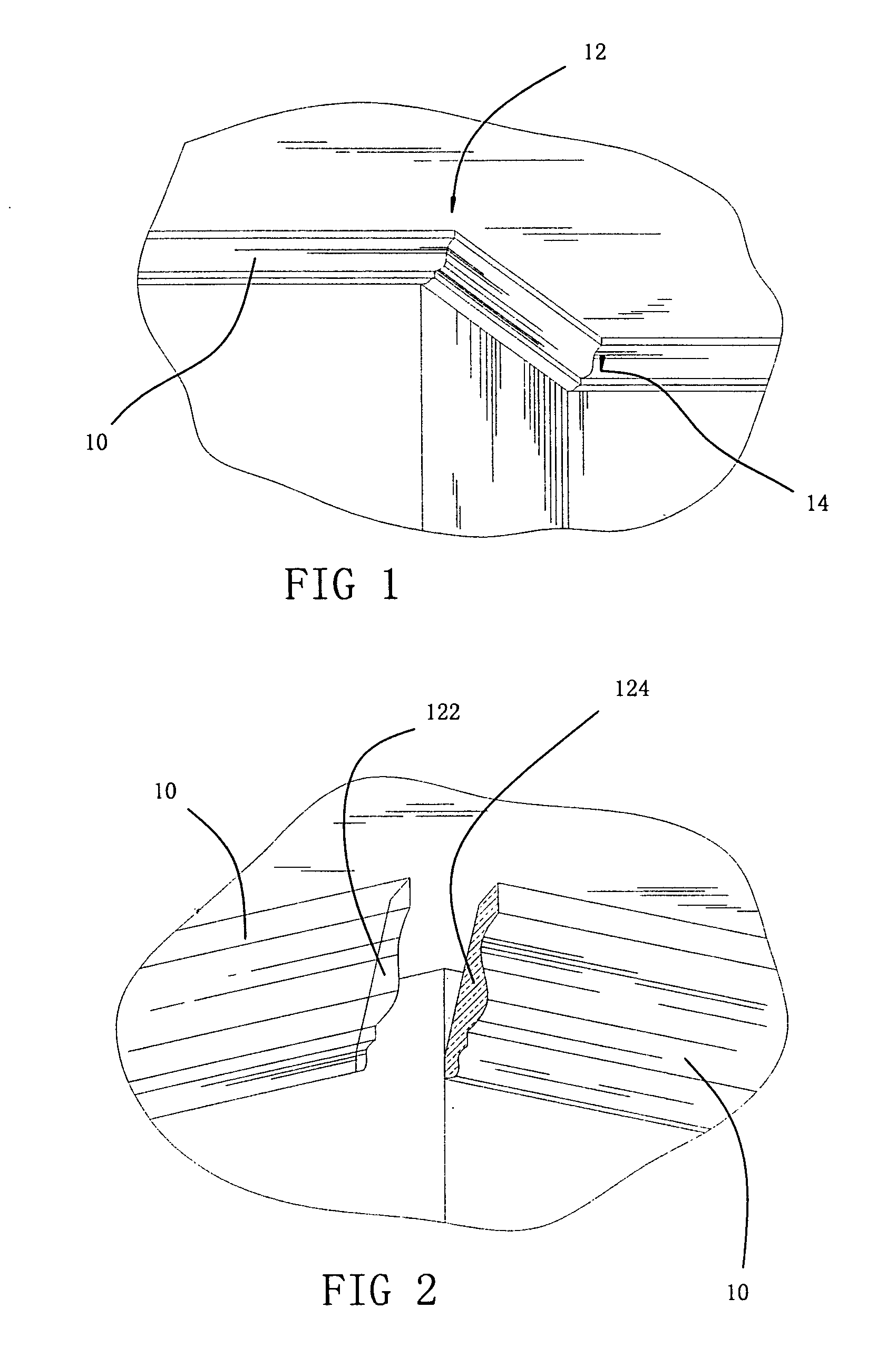
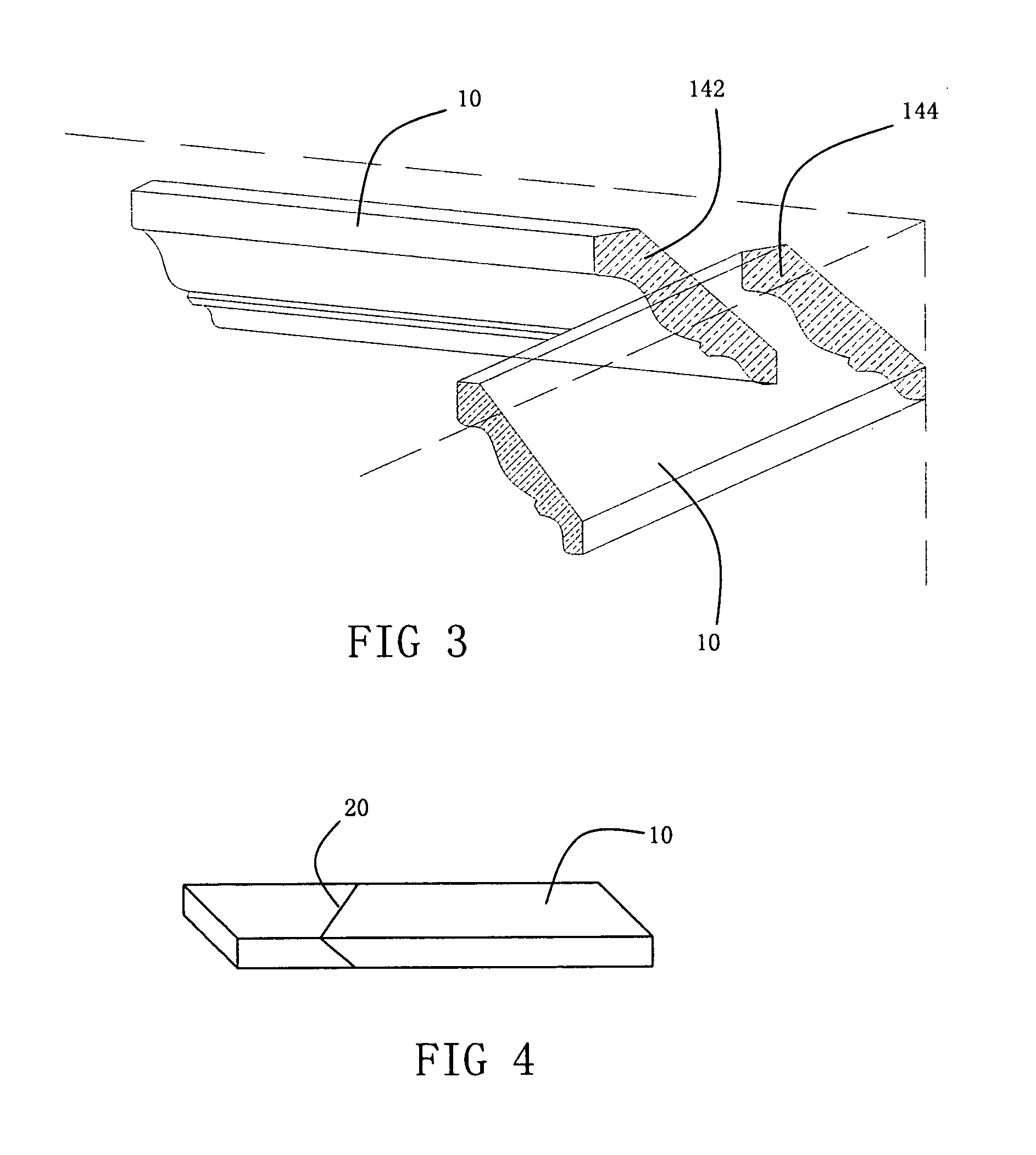
CROSS-REFERENCE TO RELATED APPLICATIONS [0001] This application claims priority to Chinese Application No. 200510123092.3 filed Dec. 15, 2005, the entire disclosure of which is incorporated herein by reference. Priority to this application is claimed under 35 U.S.C. 119, 120 and / or 365. FEDERALLY SPONSORED RESEARCH OR DEVELOPMENT [0002] Not Applicable. TECHNICAL FIELD [0003] The present invention relates to a device used for positioning and stabilizing a workpiece thereby for precisely cutting the workpiece with a cutting tool, and also relates to a method of using the stabilizing device. BACKGROUND OF THE INVENTION [0004] A crown molding is often used to add detail around the perimeter of a room's ceiling, around the tops of cabinets, or to accent lighting fixtures and skylights. A crown molding is often mounted at a certain angle to the plane to be decorated, as shown in FIG. 1. The decorative frame is formed by joining one crown molding 10 to another. As there are corners on the ...

Claims


Application Information

Patent Timeline
IPC IPC(8): B26D1/00B26D7/02B26D5/08
CPCB23D45/044B27B27/08Y10T83/8773Y10T83/7573Y10T83/04Y10T83/7684
Inventor NAGYSZALANCY, SANDOR
Owner NANJING CHERVON IND
Learn More