
Modular Single-Handed Clamping Apparatus and Method

a single-handed clamping and module technology, applied in the field of clamping apparatuses, can solve the problems of limited clamping force of existing locking clamps which allow for single-handed operation, limited application of existing individual clamps, and limited clamping force of existing locking clamps, so as to facilitate desired removal, facilitate rotation of threadably engaged elongated elements, and facilitate desired removal

Inactive Publication Date: 2022-07-07
DIMIDE INC
View PDF3 Cites 0 Cited by
  • Summary
  • Abstract
  • Description
  • Claims
  • Application Information

AI Technical Summary

Benefits of technology

The patent describes a clamping apparatus that allows for easy and secure attachment of various accessories to a power tool. The apparatus includes an upper jaw structure and a lower jaw structure with a hinge, clamp end, and nut. An elongated element is threadably engaged with the nuts of both jaw structures and can be rotated to bring the clamp ends closer together or farther apart. The apparatus can be used with different types of power tools and can be easily operated with a single hand. The technical effects of the clamping apparatus include easy attachment of various accessories, secure clamping, and efficient use of power tools.

Problems solved by technology

Existing individual clamps are limited in applications.
These clamps have fixed clamping surfaces and structures that limit their ability to be used for different applications which require different clamping surfaces, features, and / or structure.
Existing locking clamps which allow for single hand operation are limited in clamp force by the operators grip strength.
In addition, existing surface mounted clamps are limited to manual screw, or toggle mechanism which are either slow or offer little clamping force.
Alternative surface mounted clamps including hydraulic and pneumatic clamps have high price points, long setup times, cumbersome equipment, and require significant maintenance.

Method used


Image

  • Modular Single-Handed Clamping Apparatus and Method
  • Modular Single-Handed Clamping Apparatus and Method
  • Modular Single-Handed Clamping Apparatus and Method

Examples


Embodiment Construction

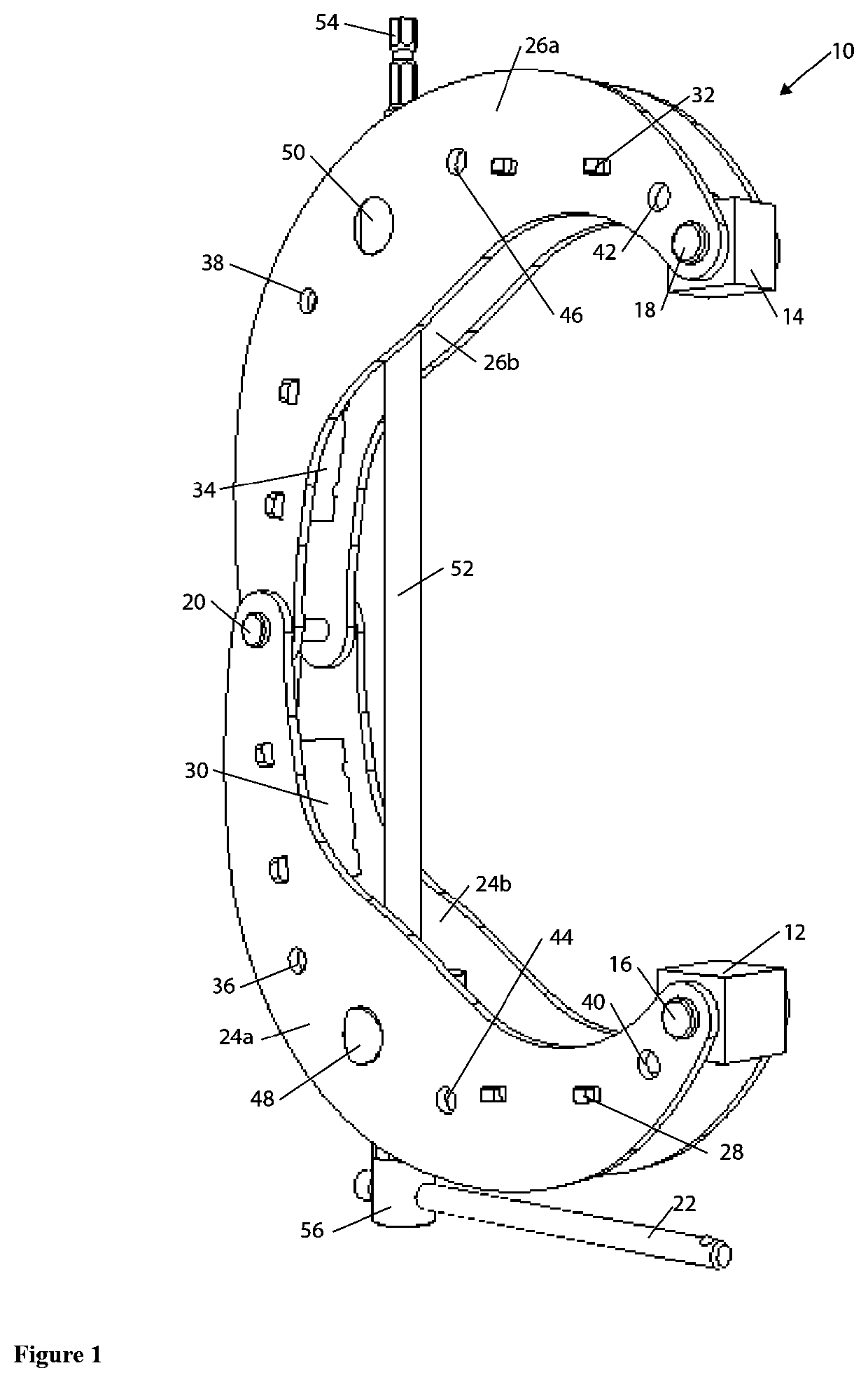
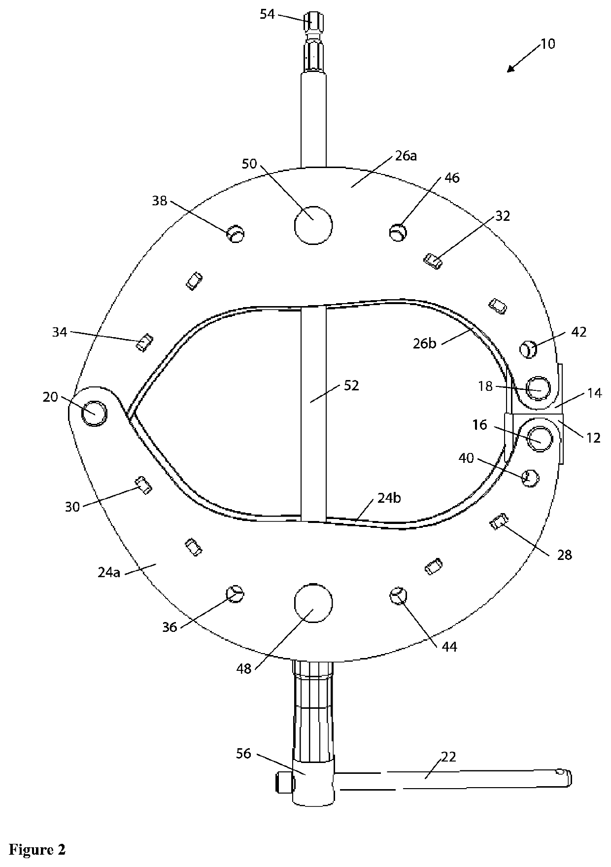
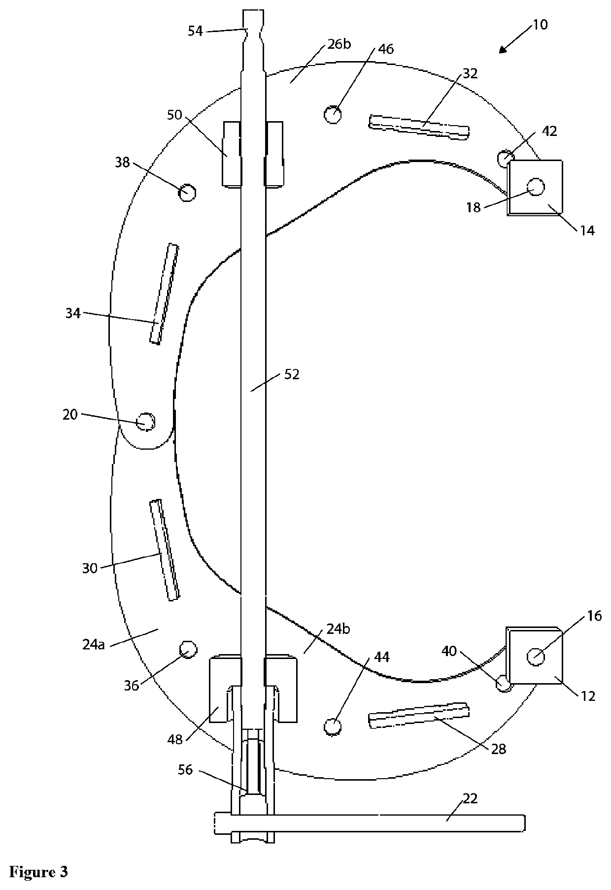
[0035]A first embodiment of a clamping apparatus 10 is shown in FIGS. 1-27. Referring now to FIGS. 1-4 showing one configuration of clamping apparatus 10. Clamping apparatus 10 having a lower jaw structure 24 and upper jaw structure 26. The lower jaw structure and upper jaw structure 24, 26 are attached in a pivotable manner at a hinge 20 located at the first end of the upper jaw and lower jaw 24, 26. The hinge connection 20 may be cylindrical which facilitates the rotation of the lower jaw structure 24 in respect to the upper jaw structure 26. The hinge 20 may be configured to resist undesired removal but facilitate desired removal without the necessity of additional tools from upper and lower jaw 24, 26, as shown in FIG. 4. The lower jaw structure 24 has a lower jaw elongated element 16 which may facilitate attaching a lower clamp jaw 12. The lower jaw elongated element 16 may be configured to resist undesired removal but facilitate desired removal without the necessity of additio...


PUM


Abstract

Disclosed herein is a clamping apparatus that is designed to be modular to facilitate use in numerous applications. In particular the modularity is fast and easy to manually perform without the need of tools. This modularity is facilitated by elongated elements which are configured to resist undesired removal, but facilitate desired removal. The modularity of the clamping apparatus is facilitated with the use of many interchangeable shoes and a variety of structural jaws. The clamping apparatus may be operated with the option of using a power tool, hand tool, or handle elongated element and may be configured to facilitate single hand operation.

Description

RELATED MATTERS[0001]This application is a nonprovisional patent application which claims priority to U.S. Provisional Application No. 62 / 266,822, filed on Dec. 14, 2015, entitled “Clamping Apparatus and Method,” and U.S. Provisional Application No. 62 / 289,487, filed on Feb. 1, 2016, entitled “Clamping Apparatus and Method,” and U.S. Provisional Application No. 62 / 957,377, filed Jan. 6, 2020, entitled “Modular Single-Handed Clamping Apparatus and Method,” the disclosure of which being herein incorporated by reference, and that builds upon technology contained in utility U.S. Pat. No. 10,307,893 B2 granted Jun. 4, 2019, entitled “Clamping Apparatus and Method,” which is hereby incorporated by reference in its entirety.FIELD OF TECHNOLOGY[0002]The subject matter disclosed herein relates generally to clamps. More particularly, the subject matter relates to a modular, and / or power tool compatible, and / or single hand operated, and / or surface mounted clamp.BACKGROUND[0003]Existing individ...

Claims


Application Information

Patent Timeline
Patent Type & Authority Applications(United States)
IPC IPC(8): B25B5/10
CPCB25B5/101B25B5/103B25B5/04B25B5/10B25B5/003
Inventor COSTEN, EMMET THOMASCOSTEN, MICHAEL KITTRIDGE
Owner DIMIDE INC
Learn More