
Artificial stone anchoring system and method

a technology of anchoring system and artificial stone, which is applied in the field of artificial stone, can solve the problems of damage to cement and joints, stone to gravitate, and it is not possible to construct a wall outdoors using such cement and stones

Inactive Publication Date: 2007-06-14
LES PIERRES STONEDGE
View PDF9 Cites 33 Cited by
  • Summary
  • Abstract
  • Description
  • Claims
  • Application Information

AI Technical Summary

Benefits of technology

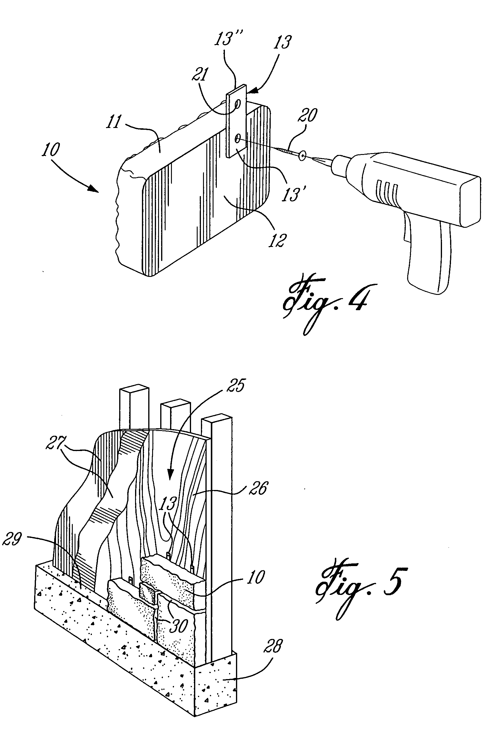
The present invention provides an improved system for anchoring artificial stones to a support surface. The artificial stones have a flat rear surface and are secured to the support surface with attachment brackets and fasteners. The attachment brackets can pivot and adjust the position of the stone, and the stone can be lifted for access. This system allows for the fabrication of stone surfaces with greater stability and flexibility.

Problems solved by technology

However, when these stones are of a larger size, the weight of the stone will have a tendency to cause the stone to gravitate in the cement texture until it abuts a lower stone and therefore needs to be repositioned.
This is time-consuming and once the cement has set these nails or screws need to be removed and this can cause damage to the cement and the joint.
A further disadvantage of the above-described system is that it is not possible to construct a wall outdoors using such cement and stones when the weather is rainy.
This is again time-consuming and a costly procedure.
A still further disadvantage of this system is that it is difficult to construct a large surface area quickly unless the installer has developed an expertise for mixing the consistency of the cement and a technique to select proper stone sizes and arrangements or pattern whereby there is minimal slippage.
A still further disadvantage is that during the construction of a wall using this system, if the installer finds that the pattern of stone is not appealing, it is difficult to change any installed stones as these are set in the cement and cannot be easily dismantled and re-arranged, at least in sections thereof.
For the above reasons, this system has proven to be labor intensive and costly.
These bricks are costly and difficult to install.

Method used


Image

  • Artificial stone anchoring system and method
  • Artificial stone anchoring system and method
  • Artificial stone anchoring system and method

Examples


Embodiment Construction

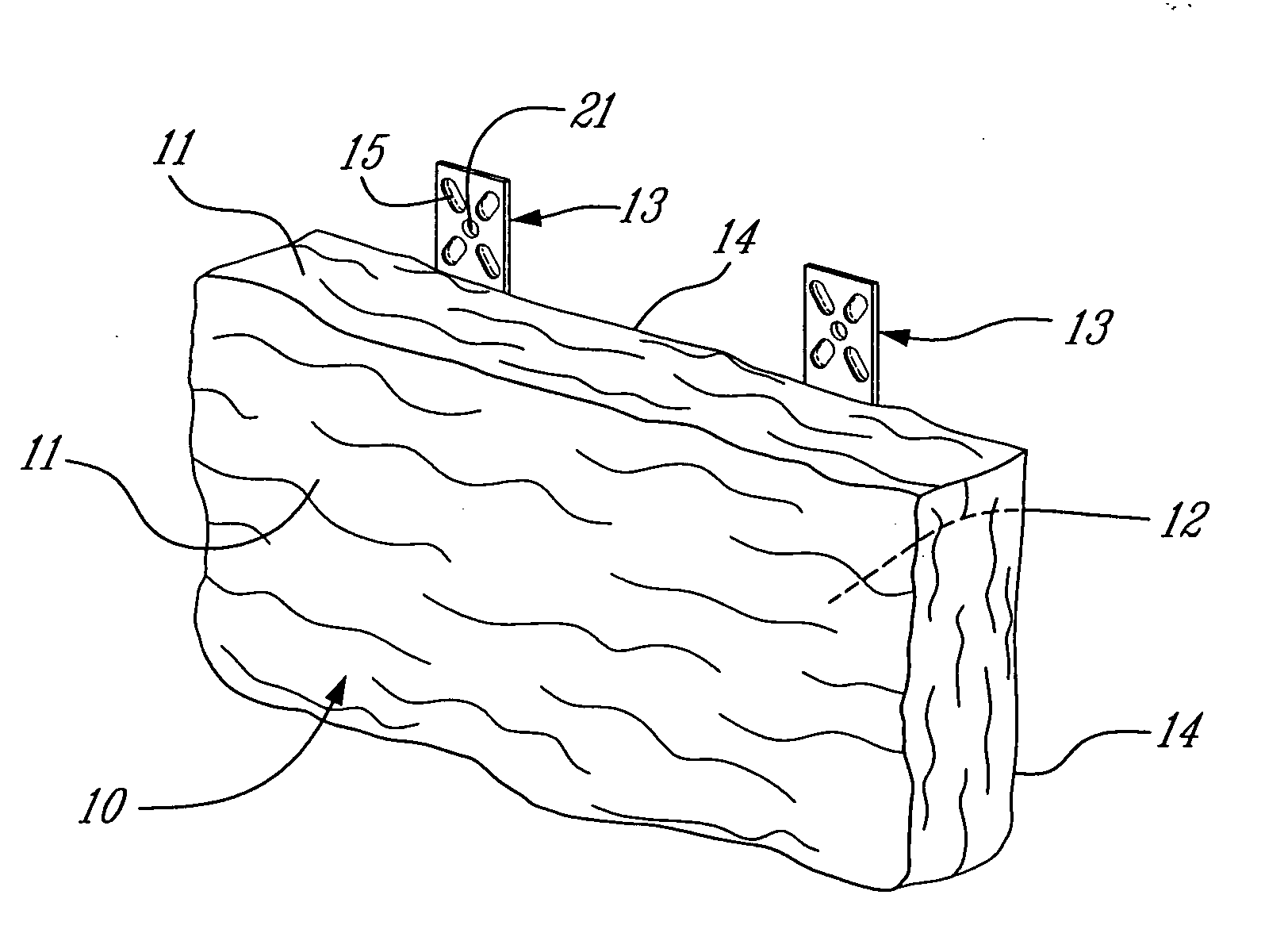
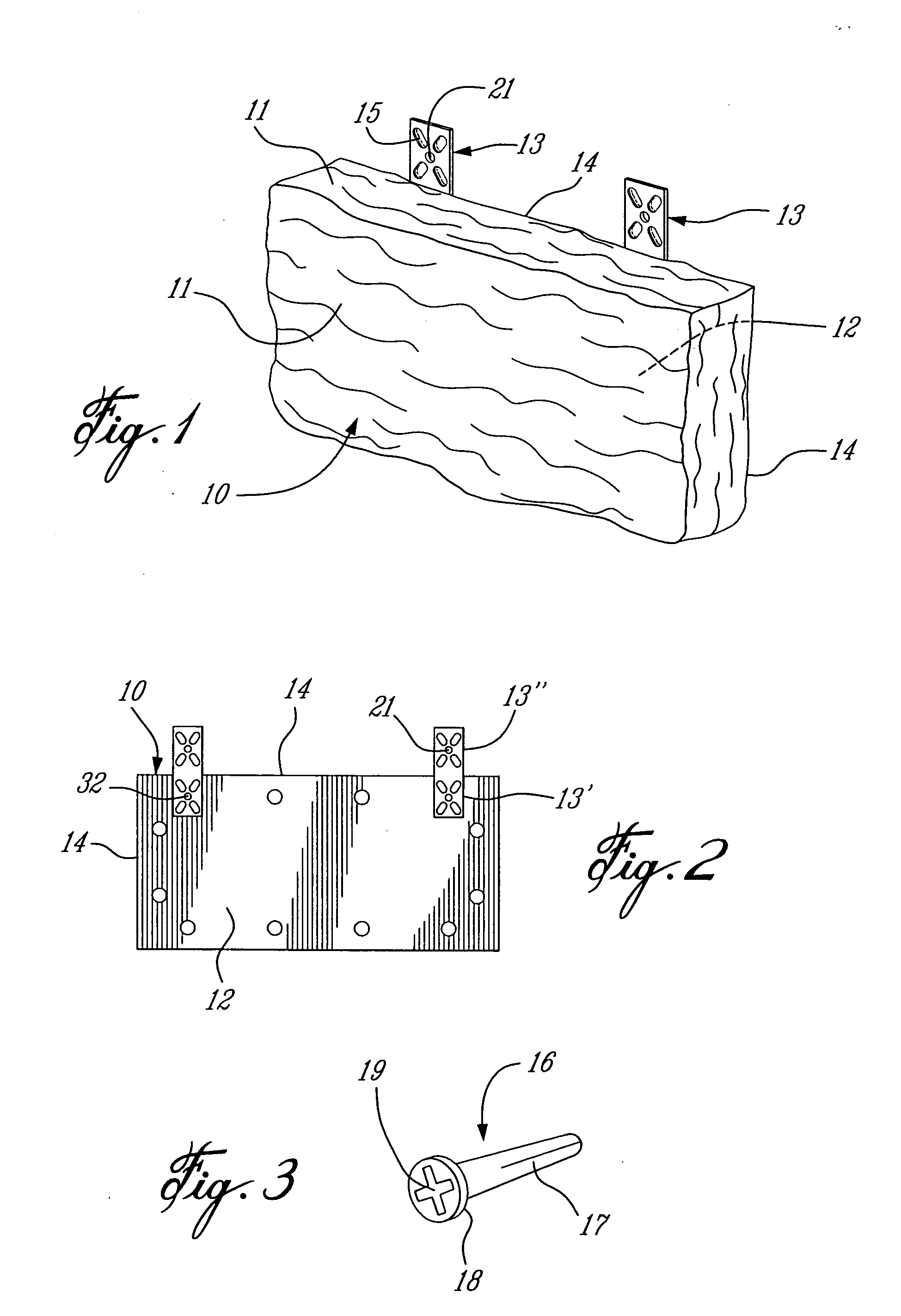
[0020] Referring now to the drawings and more particularly to FIGS. 1 to 3 there is shown an artificial stone 10 which comprises a stone body cast of a cement aggregate and having an outer visible surface area 11 extending in the front and sidewalls thereof which are shaped irregularly to resemble a real stone. The stone 10 is cast in a rubber mold formed from a real stone. A colored pigment is also incorporated in the aggregate or applied to the stone surface area 11 after casting. This stone body has a substantially flat rear surface 12 and one or more attachment brackets, herein two brackets 13, are secured to the rear flat surface 12 adjacent at least one edge 14 of the stone and project outwardly thereof.

[0021] The attachment bracket 13 is herein constituted by a flat metal strip capable of supporting the weight of the cast stone body. The bracket 13 is of rectangular outline and has a length sufficient to permit a lower section 13′ thereof to be secured on the rear surface 12...


PUM

PropertyMeasurementUnit
surface areaaaaaaaaaaa
weightaaaaaaaaaa
lengthaaaaaaaaaa

Abstract

An artificial stone and a method of fabricating a stone surface area therewith are described. The artificial stone comprises a stone body cast of a cement aggregate and has an outer visible surface area shaped to resemble a real stone. The stone body has a substantially flat rear surface. Fastener means are provided to secure one or more attachment brackets to the rear surface and adjacent at least one edge portion of the stone body to suspend the artificial stone on a support surface. The stone body is preferably cast with a light aggregate including polymeric particles.

Description

TECHNICAL FIELD [0001] The present invention relates to an artificial stone and its anchoring system and method of fabricating a stone surface area therewith. BACKGROUND ART [0002] Artificial stones and bricks have been known for several years and there exist a few systems for the securement thereof. One well known system uses an artificial stone commonly known as a “cultured stone” and it is affixed to a wall surface by a mortar cement which is trowelled on a specially prepared surface. In order for the cement to adhere to vertical surfaces it is necessary that a waterproof construction paper and a metal mesh be attached to the surface whereby to hold the cement in place. It is important also that the consistency of the cement be sufficiently tacky, that is to say not liquidly, in order for the stone to be retained thereby. These stones are fabricated with a substantially flat rear surface and by placing the stone on the cement and applying pressure against the stone a suction is c...

Claims


Application Information

Patent Timeline
Patent Type & Authority Applications(United States)
IPC IPC(8): E04F15/00
CPCE04F13/0835E04F13/0862E04F13/147
Inventor PAQUETTE, MICHELGAUVREAU, NICOLAS
Owner LES PIERRES STONEDGE
Learn More