
Liquid-condition detection element and detection sensor

Inactive Publication Date: 2007-06-07
NGK SPARK PLUG CO LTD
View PDF8 Cites 15 Cited by
  • Summary
  • Abstract
  • Description
  • Claims
  • Application Information

AI Technical Summary

Benefits of technology

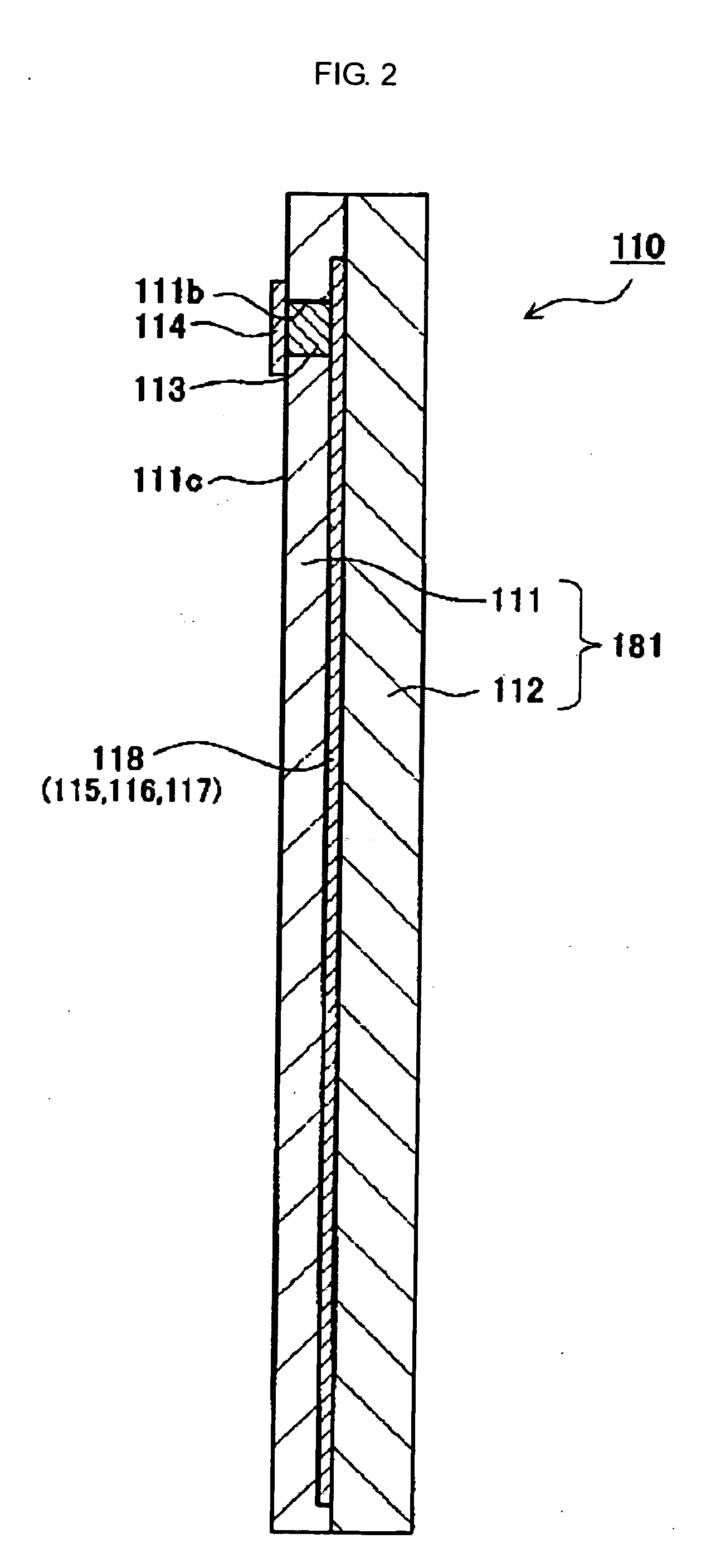
[0005] One important aspect of the present invention concerns overcoming the problems of the prior art device. To this end, there is provided a liquid-condition detection sensor having a liquid-condition detection element (hereinafter sometimes referred to merely as “element”) configured such that a heat-generating resistor is sealed in a ceramic substrate formed in a laminated structure comprised of a first ceramic insulating layer and a second ceramic insulating layer (refer to Japanese Patent Application No. 2005-200808). Sealing the heat-generating resistor in the ceramic laminate eliminates the risk of entry of liquid into the element. Thus, the element can be directly immersed in the liquid. Therefore, as compared with an element molded with resin as in the device described above, sensitivity is enhanced.
[0047] In the liquid-condition detection sensor of the present invention, as mentioned previously, the liquid-condition detection element has appropriate strength and exhibits good sensitivity. Thus, in a low-temperature environment, the liquid-condition detection sensor of the present invention is not subject to breakage of the liquid-condition detection element, which could otherwise result from a change in conditions (freezing and melting) of the urea aqueous solution, and can detect the condition of the urea aqueous solution with good accuracy.

Problems solved by technology

A disadvantage of the urea-concentration-determining device described above is that, in order to prevent entry of a urea aqueous solution into the element (i.e., the thin-film chip), the element (the thin-film chip) is molded with resin.
In this urea-concentration-determining device, since the thermal conductivity of resin is low, conduction of heat to the urea aqueous solution is difficult.
Thus, molding the element (the thin-film chip) with resin causes difficulty in raising the temperature of the urea aqueous solution.
Therefore, the difference in temperature variation of the temperature-sensing element derived from a difference in the concentration of urea in the urea aqueous solution is small and difficult to detect.
In other words, the urea-concentration-determining device does not exhibit good sensitivity in detecting changes in the temperature of the element (the thin-film chip) and thus fails to provide an accurate determination of the concentration of urea.
Thus, a liquid-condition detection sensor which uses such an element may suffer with respect to reliability.
The associated great change in the volume of the liquid (solid) results in a large force being exerted on the element.

Method used


Image

  • Liquid-condition detection element and detection sensor
  • Liquid-condition detection element and detection sensor
  • Liquid-condition detection element and detection sensor

Examples


Embodiment Construction

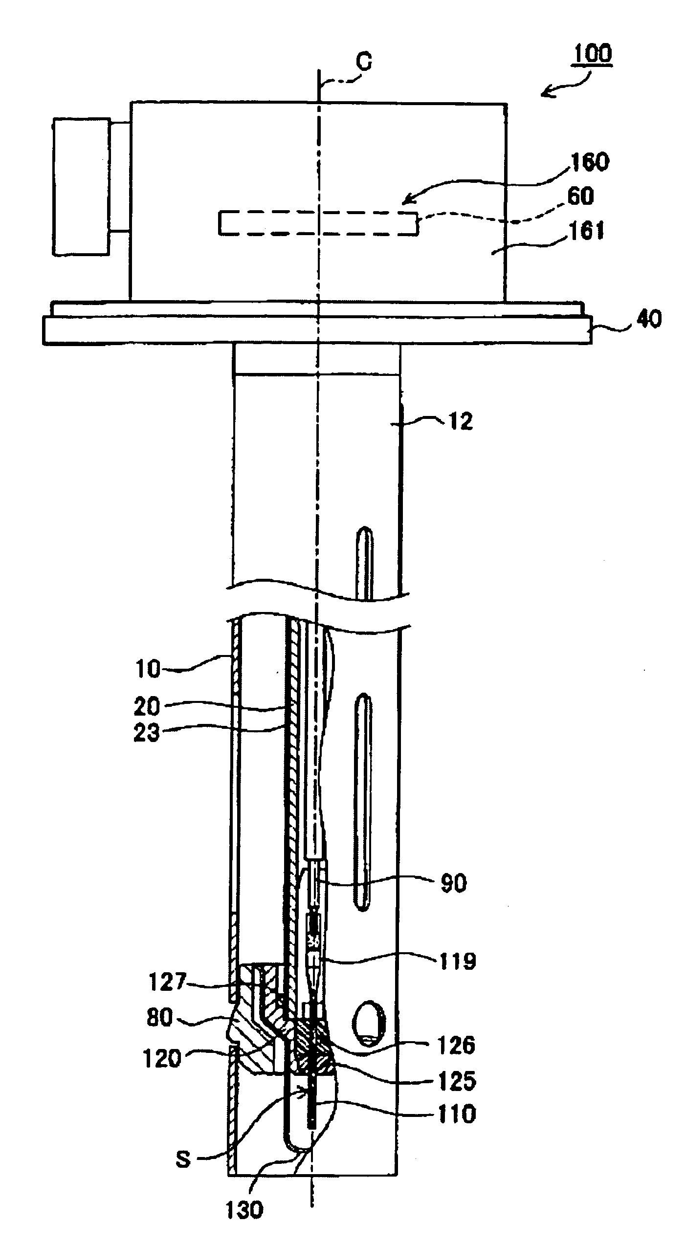
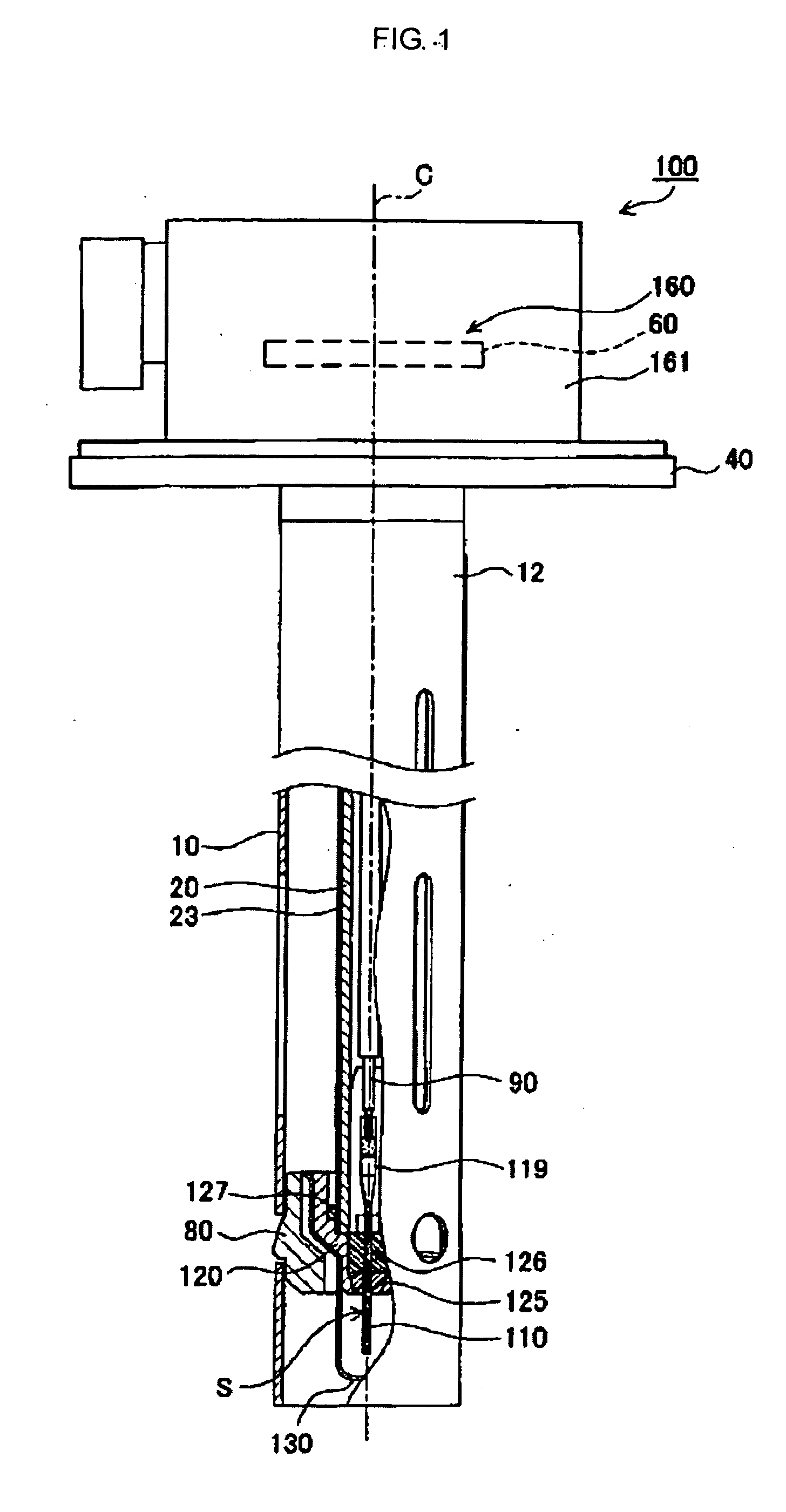
[0055] An embodiment of the present invention will be described with reference to the drawings. FIG. 1 is a partial cross-sectional view of a liquid-condition detection sensor 100 according to one preferred embodiment of the present invention. As shown in FIG. 1, the liquid-condition detection sensor 100 includes a liquid-condition detection element 110, an outer, tubular electrode 10, an inner, tubular electrode 20, a detection section 160, and a mounting section 40. In the liquid-condition detection sensor 100, as viewed along a longitudinal axis C, the side facing toward the liquid-condition detection element 110 is a front end side, and the side facing toward the detection section 160 is a rear end side. As shown in FIG. 4, in the liquid-condition detection sensor 100 of this embodiment, a front end portion thereof is immersed in a urea aqueous solution L contained in an aqueous-urea tank 98, whereby the condition of the urea aqueous solution L can be detected.

[0056] The mounti...


PUM


Abstract

A liquid-condition detection element is provided which exhibits good sensitivity while having appropriate strength. The detector element forms part of a liquid-condition detection sensor in which breakage of the detection element is combated and which can accurately detect the condition of liquid. The detection element includes first and second ceramic insulating layers formed by simultaneous firing and a heat-generating resistor sealed in a liquid tight manner between the insulating layers. The resistor has a resistance varying with temperature, and is, in use, immersed in liquid. The first insulating layer is thinner than the second layer. A detection section of the liquid-condition detection sensor detects the condition of a liquid (e.g., the concentration of a particular component in the liquid) on the basis of an output signal from the heat-generating resistor.

Description

TECHNICAL FIELD [0001] The present invention relates to a liquid-condition detection element and a liquid-condition detection sensor using the same. BACKGROUND ART [0002] Some exhaust gas purification systems for reducing nitrogen oxides (NOx) emitted from a diesel-powered automobile use an NOx selective catalytic reduction (SCR) system. The SCR system uses a urea aqueous solution as a reducing agent. Using a urea aqueous solution having a urea concentration of 32.5 wt % is known to be effective for efficiently carrying out the reducing reaction. However, the urea aqueous solution contained in an aqueous urea tank mounted in a diesel-powered automobile may vary in urea concentration because of variations over time or for other reasons. Also, a different solution (e.g., light oil), water, or the like may be erroneously mixed in the aqueous urea tank. In view of these problems, in order to control the condition of liquid (i.e., the urea concentration in urea aqueous solution) in the a...

Claims


Application Information

Patent Timeline
IPC IPC(8): G01N33/18G01N17/04
CPCF01N3/2066F01N11/00F01N2610/02F01N2900/1818G01N27/14
Inventor SASANUMA, TAKEOSATO, YOSHIKUNIMIZUNO, YUKI
Owner NGK SPARK PLUG CO LTD
Learn More