Eureka AIR delivers breakthrough ideas for toughest innovation challenges, trusted by R&D personnel around the world.

Lighting or signaling device with an optical guide for a motor vehicle

a technology of light or signaling device and optical guide, which is applied in the direction of lighting and heating apparatus, instruments, transportation and packaging, etc., can solve the problems of difficult to ensure a homogeneous appearance, difficulty in ensuring uniformity, and insufficient broad distribution of light emerging from the guide, etc., to achieve the effect of simple

Active Publication Date: 2007-05-31
VALEO VISION SA
View PDF18 Cites 27 Cited by
  • Summary
  • Abstract
  • Description
  • Claims
  • Application Information

AI Technical Summary

Benefits of technology

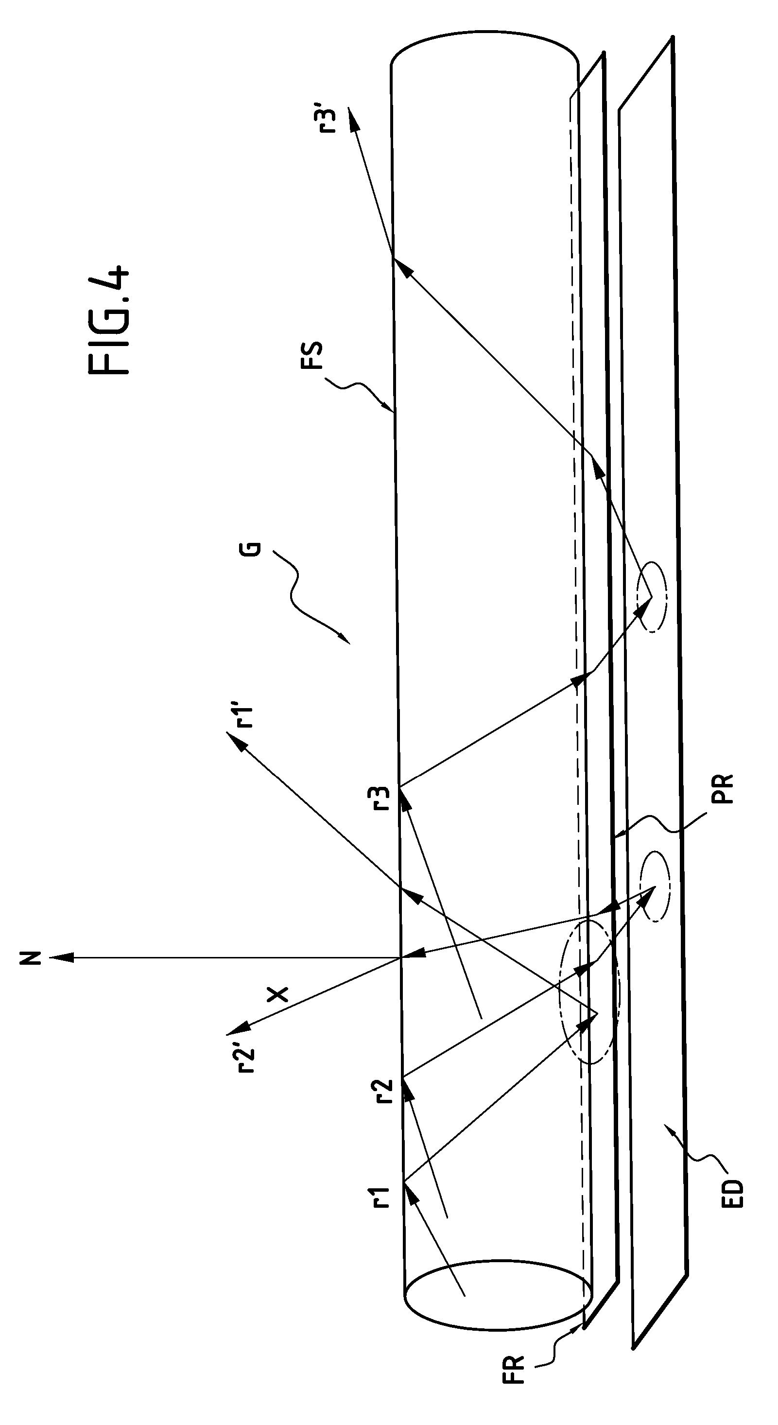
[0010] It has been possible to show that the presence of this diffusing element had, surprisingly, a significant impact on the illuminated appearance of the guide: it makes it possible in fact to recuperate the light escaping from the guide from its rear face and to return it at least partly into the guide with a high angular width, because of its diffusing character. This has two advantageous consequences: the guide has a higher optical efficiency, and it emits a more spread light through its front face, with a more anisotropic direction: from wherever it is observed, the guide keeps a fairly homogeneous illuminated appearance, whilst in the absence of a diffusing element the guide has an appearance that is little or not illuminated nor homogeneous at a high angle of incidence, as soon as one moves away from an angle of vision corresponding to the longitudinal axis of the vehicle in particular.
[0016] The diffusing screen can be fixed to or form an integral part of a mask of the device. A mask (bezel in English) is understood to be a style part for ensuring continuity of surface between, for example, a reflector and the edge of a housing or the headlight or light lens. The bezel may have various appearances, in particular matt or on the contrary bright and approaching the appearance of the reflector. Integrating the diffusing screen according to the invention in a bezel associated with a reflector of a main lighting or signaling function is technically advantageous: no additional part is added, and there is a gain in simplicity of assembly and in tolerance in positioning between the components of the light or headlight overall. The diffusing screen can form an integral part of a bezel of the device, by local modification of the surface properties / appearance of the said bezel, in particular by surface erosion, or addition or elimination of a coating. It may for example be a case of an aluminized bezel, an area of which has no layer of aluminum and is possible frosted in order to have a sufficient level of diffusing power.
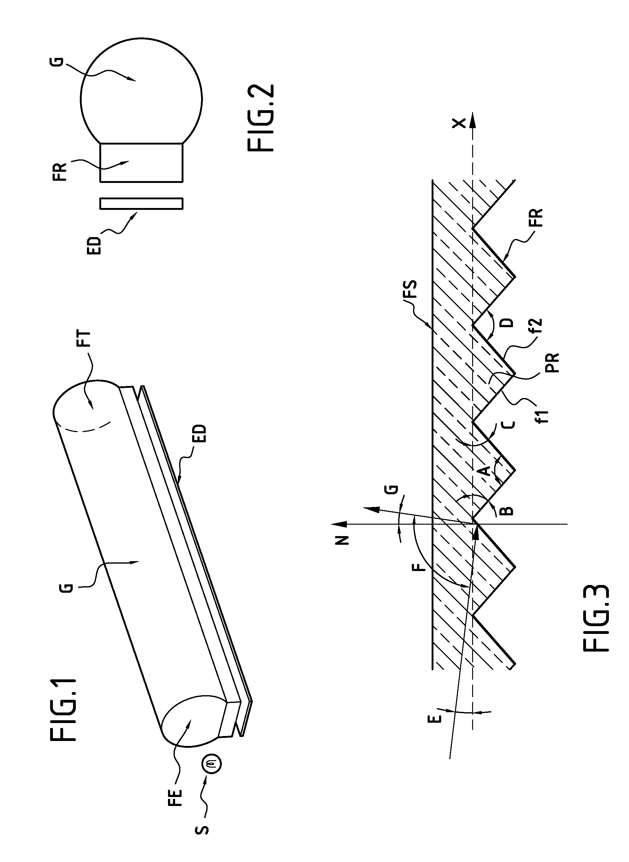
[0018] It is advantageous for the diffusing screen not to be too close or even in direct contact with the guide: a distance of at least 0.5 mm between the diffusing screen and the reflection face of the guide is generally chosen, in particular a distance between 1 and 5 mm. The efficacy of the screen is improved thereby, the rays re-diffused by the screen then having sufficient path to travel before once again entering the guide in order to spread out with the wide angular amplitude sought.
[0021] Modification of the guide is simple to achieve, since it is possible to preserve the design of the known light guides and to add this diffusing screen thereto.

Problems solved by technology

However, existing light guides are open to improvement: this is because it is often tricky to ensure an identical illumination level between the first and second ends of the guide, particularly if it has a significant length, the illumination level having a tendency to decrease on moving away from the entry face of the guide.
Moreover, it is also tricky to ensure a homogeneous appearance to the guide whatever the angle of vision that there is of the guide, the light emerging from the guide having an angular distribution that is often insufficiently broad.

Method used


Image

  • Lighting or signaling device with an optical guide for a motor vehicle
  • Lighting or signaling device with an optical guide for a motor vehicle
  • Lighting or signaling device with an optical guide for a motor vehicle

Examples


Embodiment Construction

[0028] All these figures are highly schematic and are not necessarily to scale in order to facilitate the reading thereof.

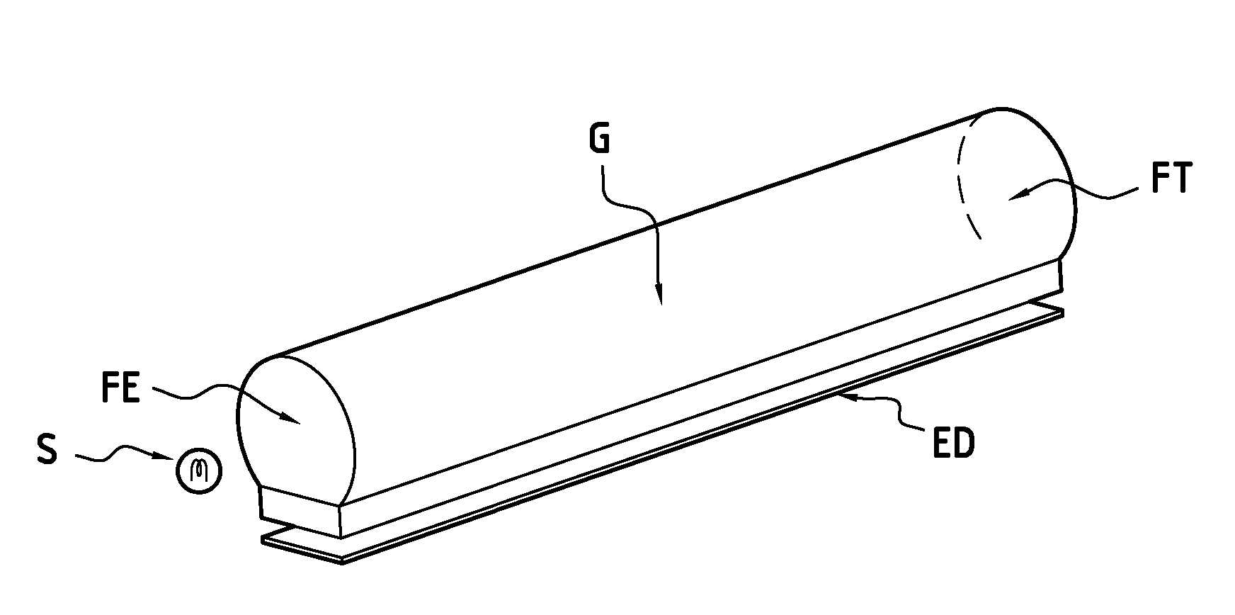
[0029]FIGS. 1 and 2 show a view in perspective and cross section of an optical guide G intended to propagate a light beam emitted by a light source S. The optical guide in this example is rectilinear.

[0030] Naturally the optical guide according to the invention can have other forms such as for example comprising curvatures, one or more portions of an arc of a circle, etc. The invention also applies to these curved guides mutatis mutandis.

[0031] In this embodiment, the optical guide G has a circular cross section; naturally it can also, in other embodiments, have an elliptical, square, oval or even square etc. cross section.

[0032] In this embodiment, the optical guide G is based on transparent polymer, polycarbonate (or polymethyl methacrylate PMMA), preferably of crystal quality.

[0033] This optical guide has a so-called entry face FE at one of its ends, oppo...


PUM


Abstract

A lighting and / or signaling device for a motor vehicle, comprising at least one light source emitting a light beam and at least one optical guide in which the light beam propagates, the optical guide comprising: a first face forming an exit face for the light beam, and a second face, opposite to the exit face, forming a reflection face for the light beam, such that the light guide is associated with a diffusing screen disposed opposite the reflection face of the light guide.

Description

BACKGROUND OF THE INVENTION [0001] 1. Field of the Invention [0002] The object of the present invention is a lighting or signaling device equipping a motor vehicle, comprising at least one optical guide able to produce diffusion of the light over at least part of its length. The invention also concerns a vehicle comprising such a lighting or signaling device. [0003] 2. Description of the Related Art [0004] In the field of motor vehicle lighting and signaling, optical guides are being used more and more frequently. An optical guide is, very schematically, an elongate element made from transparent material, generally in the form of a cylinder. Close to one of the ends of the guide, referred to as the guide entry face, one (or more) light source is disposed, for example a small light source of the light emitting diode type: the light rays emitted by this source propagate by total reflection in the length of the guide in the direction of its opposite end, referred to as the end face of ...

Claims


Application Information

Patent Timeline
IPC IPC(8): B60Q1/00F21W107/10
CPCF21S48/2237F21S48/2268F21S48/2281G02B6/0001G02B6/0051G02B6/0053G02B6/0055F21S43/237F21S43/249F21S43/245F21S43/40
Inventor BOURDIN, DAVIDDUBOSC, CHRISTOPHEMULLER, JULIEN
Owner VALEO VISION SA
Why Eureka
Eureka Blog
Learn More