Phase-locked loop

a phase-locked loop and phase-locked technology, applied in the direction of digital transmission, pulse automatic control, tire measurement, etc., can solve the problems of insufficient data communication in many applications, tire pressure monitoring system no longer functional, and inability to use the settling time for data communication, etc., to reduce the settling time of the phase-locked loop

Inactive Publication Date: 2007-05-31
ATMEL AUTOMOTIVE
View PDF10 Cites 4 Cited by
  • Summary
  • Abstract
  • Description
  • Claims
  • Application Information

AI Technical Summary

Benefits of technology

[0015] It is therefore an object of the present inv...

Problems solved by technology

However, the settling time cannot be used for data communication, so there is a need to keep this as short as possible.
Now if, as in the example described above, the settling time of the phase-locked loop is relatively long, then a relativ...

Method used


Image

  • Phase-locked loop
  • Phase-locked loop
  • Phase-locked loop

Examples


Embodiment Construction

[0051] In the drawings, like or functionally like elements and signals are identified with the same reference labels, unless otherwise specified.

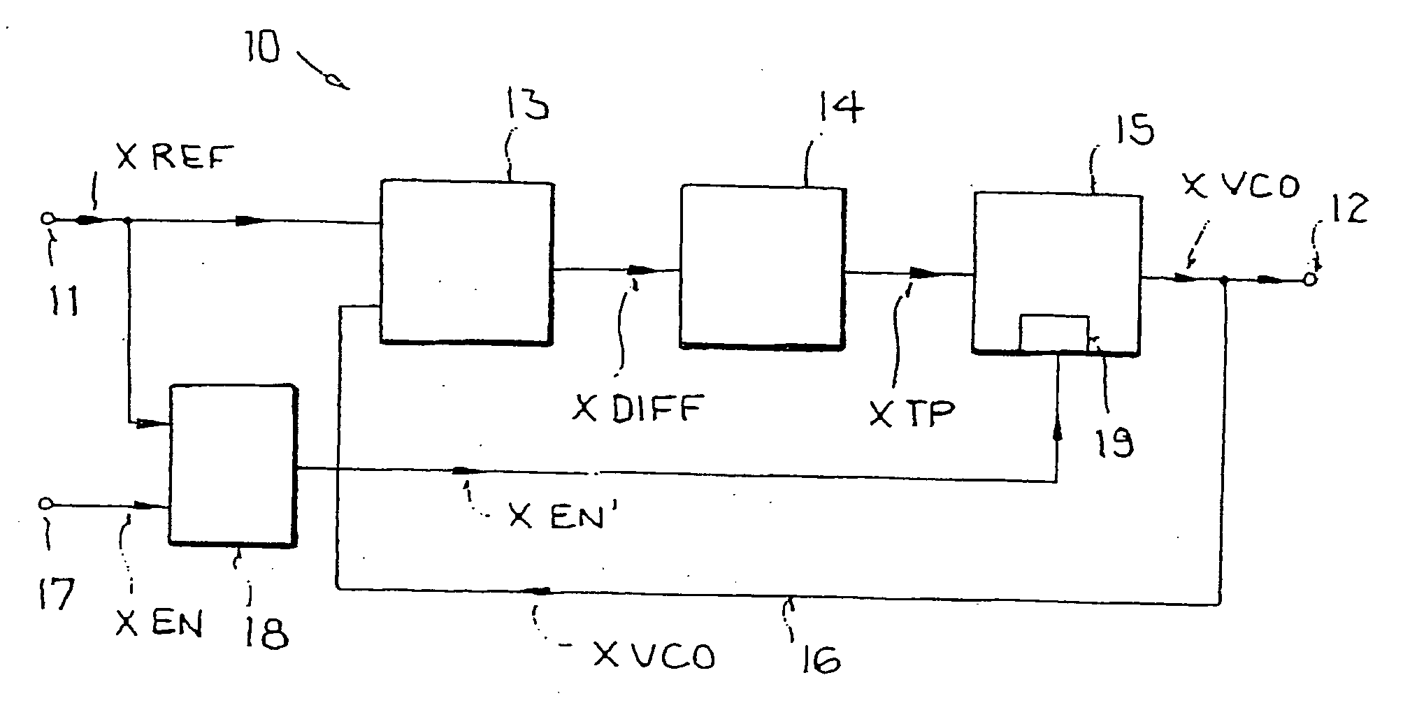
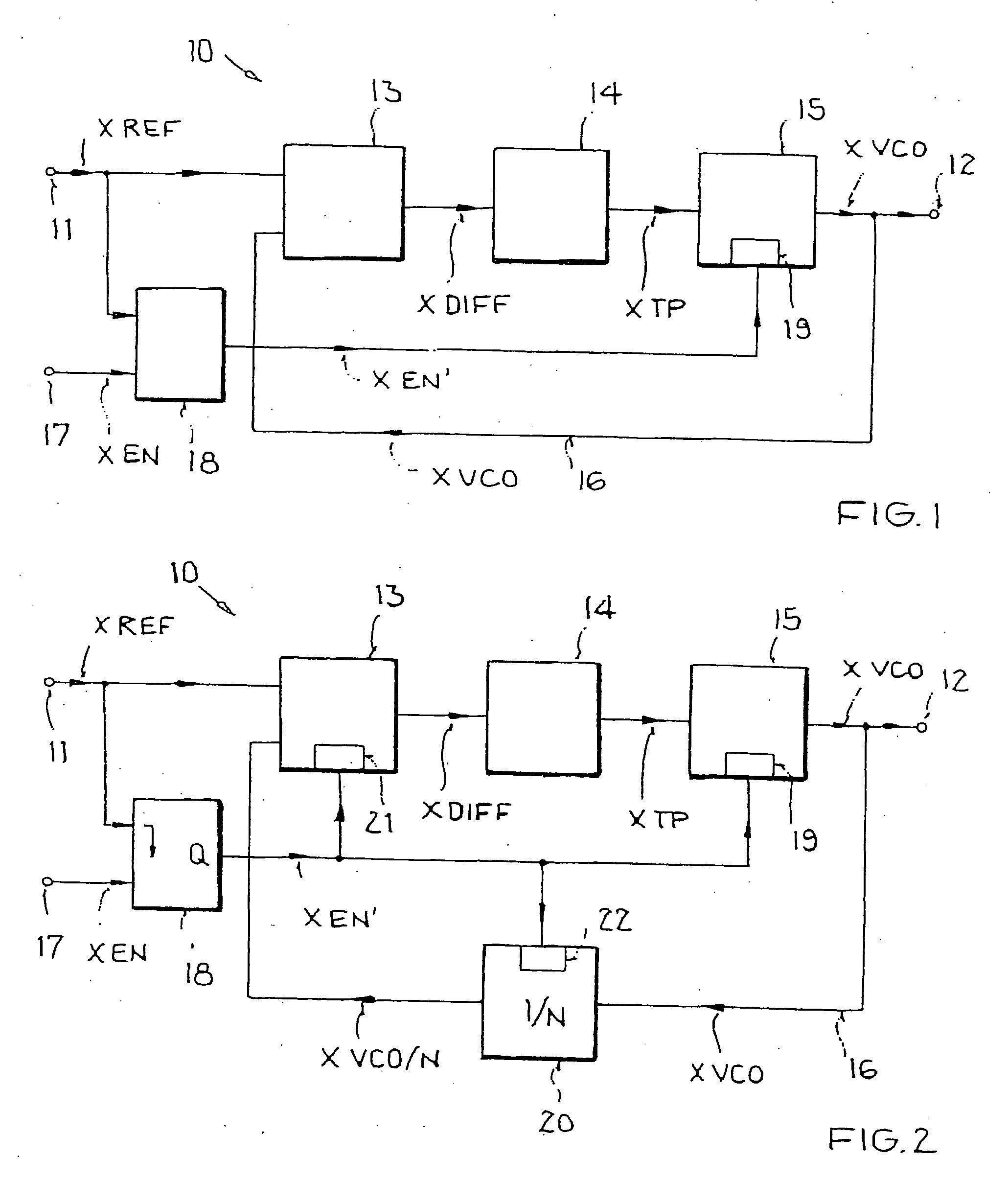
[0052]FIG. 1 shows a block diagram of an embodiment of a phase-locked loop. The phase-locked loop 10 is labeled with the reference symbol 10 here. The phase-locked loop has a reference input 11 into which a reference input signal XREF can be coupled, and an output from which an output signal XVCO can be obtained. Arranged one after the other in series between the input 11 and the output 12 are a phase comparator 13, a loop filter 14, and an oscillator 15. In addition, a feedback path 16 is provided through which the output signal XVCO can be obtained and coupled into an input of the phase comparator 13.

[0053] The phase-locked loop 10 also has another input 17, through which, e.g., a digital switch-on signal XEN can be coupled in. Moreover, a control unit 18 is provided that has two inputs and one output. Each input of the control unit 18 ...


PUM


Abstract

A phase-locked loop with reduced settling time, in particular in or for a transceiver circuit of a tire pressure monitoring system, is disclosed, The phase-locked loop includes, sequentially arranged in a signal path, phase comparators for generating a phase difference signal by comparing a reference input signal and an output signal, loop filters for filtering the phase difference signal, and an oscillator controlled by the filtered phase difference signal for generating the output signal. The phase-locked loop has an adapting circuit for reducing the settling time at switch-on of the phase-locked loop, which adapting circuit correlates the actual switch-on of the phase-locked loop with the signal behavior of the reference input signal. A transceiver circuit of a tire pressure monitoring system is also disclosed.

Description

[0001] This nonprovisional application claims priority under 35 U.S.C. § 119(a) on German Patent Application No. DE 102005056033, which was filed in Germany on Nov. 24, 2005, and which is herein incorporated by reference. BACKGROUND OF THE INVENTION [0002] 1. Field of the Invention [0003] The present invention relates to a phase-locked loop, in particular in or for a transceiver circuit of a tire pressure monitoring system, having sequentially arranged phase comparators for generating a phase difference signal from a reference input signal and an output signal, loop filters for filtering the phase difference signal, and an oscillator controlled by the filtered phase difference signal for generating the output signal. The invention further relates to a transceiver circuit of a tire pressure monitoring system. [0004] 2. Description of the Background Art [0005] Phase-locked loops (PLL) have wide application in electronics, and are used to generate and synchronize clock signals, for exa...

Claims


Application Information

Patent Timeline
IPC IPC(8): H03L7/06B60C23/00H04L27/00
CPCH03L7/087H03L7/095H03L7/10
Inventor TYULPANOV, ALEXANDER
Owner ATMEL AUTOMOTIVE
Why Eureka
Try Eureka