
Personal fit medical implants and orthopedic surgical instruments and methods for making

a technology of orthopedic surgical instruments and implants, applied in the field of personal fit medical implants and orthopedic surgical instruments and methods for making, can solve the problems of inability to meet the approval criteria, inability to remove otherwise healthy or undamaged tissue, and inability to achieve optimal fit in most cases, so as to minimize the effect of ni toxicity

Inactive Publication Date: 2007-05-24
VANTUS TECH CORP
View PDF31 Cites 566 Cited by
  • Summary
  • Abstract
  • Description
  • Claims
  • Application Information

AI Technical Summary

Benefits of technology

[0010] In this method, preferably, the input imaging data is received from MRI, X-Ray, CT, ultrasound, LASER interferometry or PET scanning of the patient. This imaging data is then used to derive a 3D CAD solid model which is used for computer aided engineering (CAE) analyses such as finite element analysis (FEA), behavior modeling and functional component simulation. A 3D CAD solid model is used to derive an FEA model for modeling biological tissue for the target patient and for FEA of differing materials. The 3D CAD solid model is also used for computer aide manufacturing (CAM). A 3D CAD solid model provides excellent visualization for design validation and will be used as such.
[0015] In another preferred embodiment, the device is a bone prosthesis and the fabrication materials are Ti6-4 in combination with cpTi. More preferably, the fabrication material is Nitinol (NiTi) alloy, such that the device surface is substantially made of Ti for minimizing Ni toxicity.

Problems solved by technology

However, this protocol does not always meet with success.
Often the surgeon must choose between one size that is too large and another that is too small, or another that is close but not quite the correct shape.
Although surgeons can often improvise the fit through selective removal of the patient's bone, removing otherwise healthy or undamaged tissue is not desirable, and the fit will in most cases still be less than optimal.
In some cases it may be possible for the surgeon to modify the device to make a better fit, but it is not generally feasible to machine, bend, grind, drill or otherwise modify the structure of the very tough materials used in orthopedic devices within the constraints of the operating theater.
While such methods discuss three dimensional imaging of the implant site and design of implantable device they are limited to uses for rapid prototyping and do not allow for the production of an actual prosthesis or usable article.
In such cases the length, size and grip of an instrument are generally not available in hybrid sizes, custom designs or custom alloy mixtures.
In such cases, the physician or end-user is limited to the best fit, weight or alloy available.

Method used


Image

  • Personal fit medical implants and orthopedic surgical instruments and methods for making
  • Personal fit medical implants and orthopedic surgical instruments and methods for making
  • Personal fit medical implants and orthopedic surgical instruments and methods for making

Examples


examples

Preferred Exemplary Embodiments

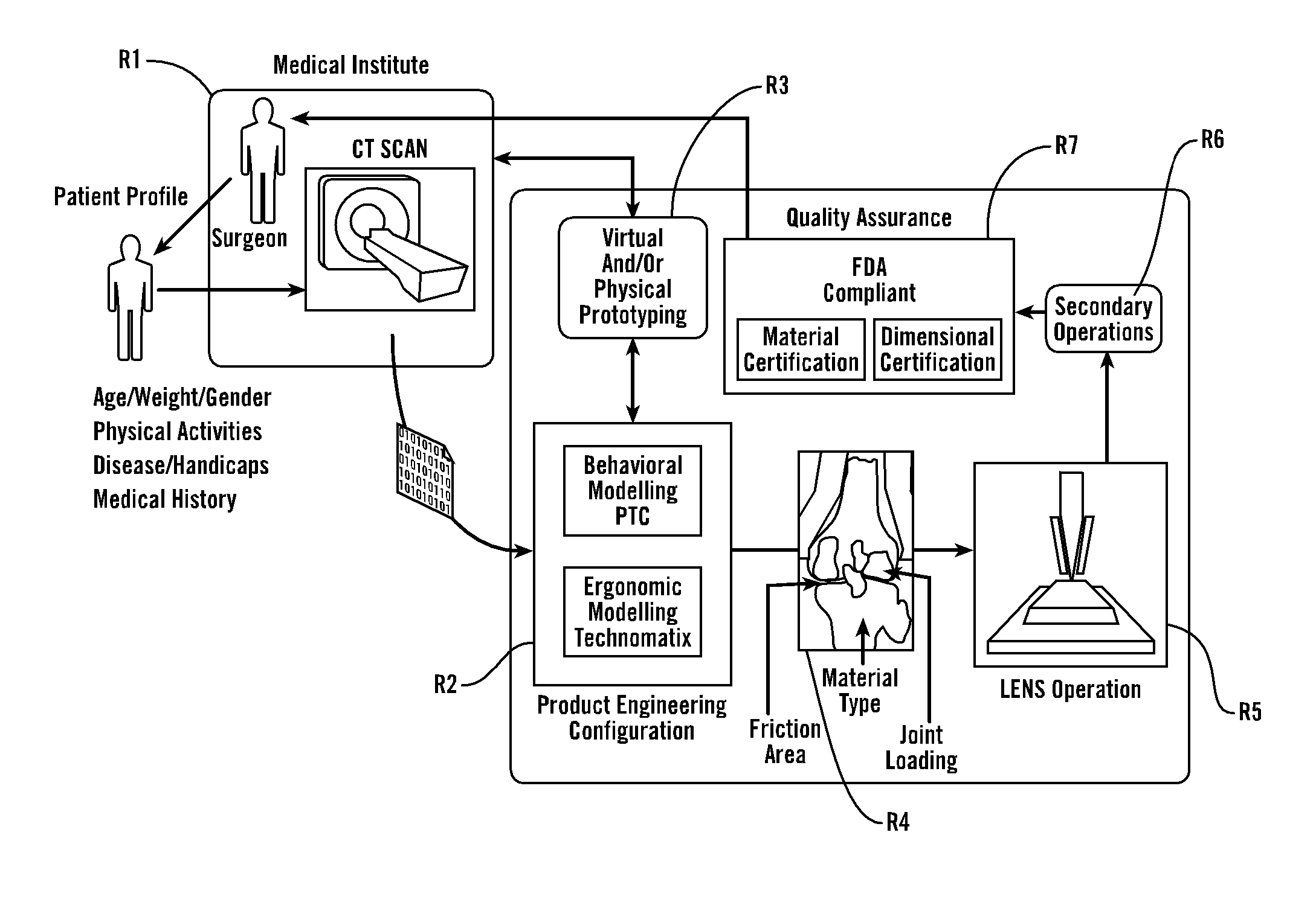
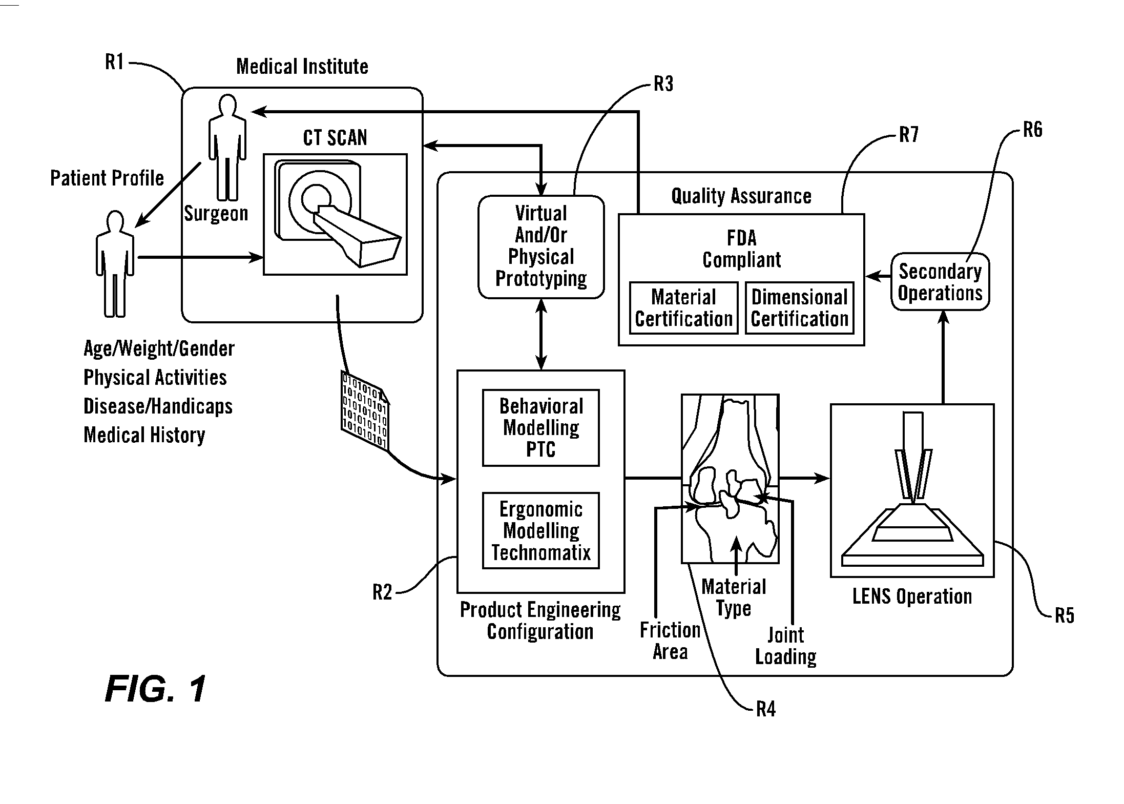
[0066] As shown in FIG. 1, in a preferred embodiment, the present invention provides methods and tools to produce implantable medical devices that will precisely fit individual patients. The present invention also comprises medical appliances and tools and implements designed and created through the disclosed process. Generally, the invention is implemented through a combination of technologies including medical imaging (including CT, NMR, X-ray, ultrasound, laser interferometry and others) and patient consultation R1. Next, the product engineering configuration R2 analysis is implemented using both behavioral modeling (WHAT IS PTC?) and ergonomic modeling technomatix analysis. Next, virtual and / or physical prototyping is performed R3 which allows for validation of the product engineering results by further reference with R1. Then, in R4, analysis of the implant site identifies the friction area, analyzes the joint loading and identifies material type...

example i

Image Acquisition and Analysis

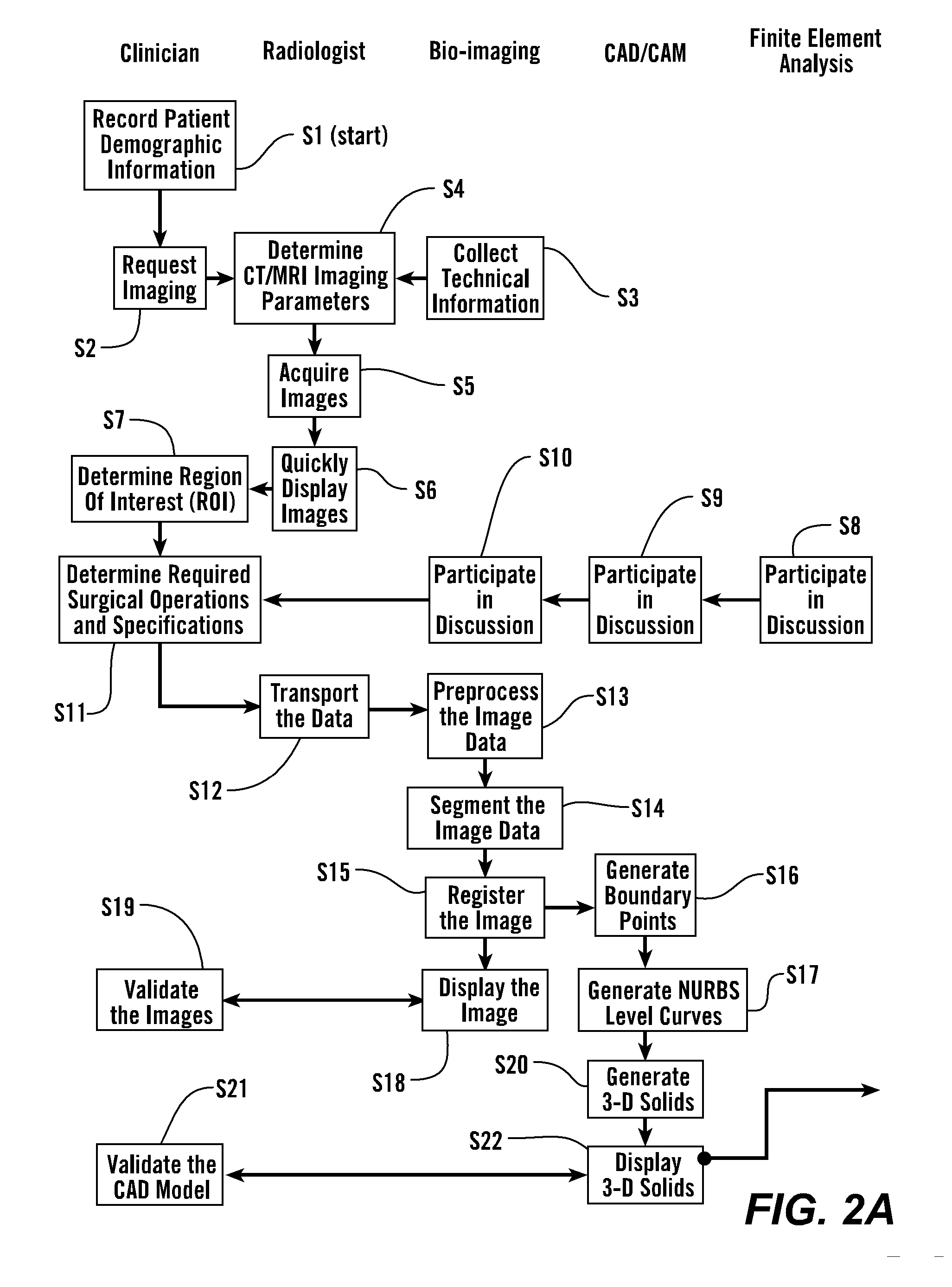
[0067] As shown in FIGS. 2A and 2B, in some embodiments, the process starts with step S1 where the patient's demographic information is recorded and the clinician makes a request for imaging, S2. 3-Dimensional image data is obtained from the patient S4 and presented for clinical evaluation with the cooperation of multiple specialists, S3 and using the invention described herein (FIGS. 1 and 2A). This uses multiple steps as listed in Table 1, and further elaborated below.

TABLE 1Image Acquisition and Analysis1CT / MRI Image calibration2Calibration of laser surface contour scanning to determine surfacestructure as required for certain applications3Physical correlation of pixel data for precise reconstruction of thepatient's anatomical structure4In situ validation5Establish protocol for image acquisition and transport6Troubleshooting of various imaging parameters - size, intensity,orientation, spacing, etc.7Image file format, size, and transport medium8Ima...

example ii

Manufacturing

[0084] The design created above is fabricated using direct computer aided manufacturing (CAM) digital methods to produce the implant with laser-based additive free-form manufacturing as described above, S33. Fabrication of each component is performed with the desired material or materials directly from powdered metals (and certain other materials) that are delivered to the desired spatial location and then laser annealed in place (using, for example, DMD, LENS or the like) or annealed using an electron beam (EBM). This produces a very high strength fine-grain structure, enables the fabrication of internal features, enables layers of multiple materials, gradients of material properties, inclusion of ancillary internal elements, and produces resultant structures that generally require minimal post-fabrication processing.

[0085] Multiple materials are applied sequentially, locally, and in specific locations, if required to achieve desired properties For example, the bone ...


PUM


Abstract

The present invention provides methods, techniques, materials and devices and uses thereof for custom-fitting biocompatible implants, prosthetics and interventional tools for use on medical and veterinary applications. The devices produced according to the invention are created using additive manufacturing techniques based on a computer generated model such that every prosthesis or interventional device is personalized for the user having the appropriate metallic alloy composition and virtual validation of functional design for each use.

Description

[0001] This utility patent application claims the benefit of and priority to U.S. Provisional Application 60 / 596,704 filed Oct. 14, 2005, incorporated herein by reference in its entirety.FIELD OF THE INVENTION [0002] The present invention relates to methods, devices, and instruments to improve the quality of healthcare through the production of medical implants and surgical instruments that are fabricated to precisely fit individual users. This invention is implemented and based upon a combination of technologies including medical imaging, quantitative image analysis, computer aided design, computer aided manufacturing, and additive manufacturing processes that can directly produce high strength metallic and composite devices. Specifically, the present invention uses techniques of freeform manufacture to produce biocompatible articles that are personalized to the user. BACKGROUND OF THE INVENTION [0003] Medical implants have dramatically improved the quality of life for many persons...

Claims


Application Information

Patent Timeline
IPC IPC(8): G06F19/00
CPCA61B17/68A61B17/70A61B17/72A61B17/8061A61B17/8066A61B17/866A61B2017/00526A61C13/0004A61F2/28A61F2/2803A61F2/2875A61F2/30771A61F2/30942A61F2/32A61F2/34A61F2/36A61F2/3609A61F2/82A61F2002/2889A61F2002/30092A61F2002/30492A61F2002/30507A61F2002/3055A61F2002/30879A61F2002/30948A61F2002/30952A61F2002/30955A61F2002/30962A61F2002/30968A61F2002/3097A61F2002/3611A61F2002/365A61F2210/0014A61F2220/0025A61F2310/00011A61F2310/00017A61F2310/00023A61F2310/00029A61F2310/00131A61F2310/00179A61F2310/00185A61F2310/00329G05B19/4099G05B2219/35017G05B2219/35134G05B2219/35219G05B2219/45168G06F19/3437G16H50/50B33Y80/00B33Y50/00A61N1/375G16H20/40
Inventor SCHROEDER, JAMESGOODMAN, STEVEN L.KIM, KYU-JUNG
Owner VANTUS TECH CORP
Learn More