Method for making a shadow mask for an apposed discharge plasm display panel

a plasma display panel and opposed discharge technology, which is applied in the manufacture of electric discharge tubes/lamps, cold cathode manufacture, electrode systems, etc., can solve the adverse effect of luminescence efficiency of opposite discharge plasma display panels, high difficulty, and high manufacturing cost, so as to reduce the risk of chemical pollution, improve the product yield rate, and reduce the difficulty

Inactive Publication Date: 2007-05-24
MARKETECH INT
View PDF6 Cites 2 Cited by
  • Summary
  • Abstract
  • Description
  • Claims
  • Application Information

AI Technical Summary

Benefits of technology

[0009] Therefore, it is a primary objective of the present invention is to etch a plurality of parallel and equidistant barrier ribs along the vertical and horizontal directions and on a side of a metal slab by an etching process, and form a discharging cell by enclosing every four adjacent barrier ribs. A shadow hole is disposed at the middle of each discharging cell and etched through the metal slab, and at least one groove interconnected to the shadow hole is produced on another side of the metal slab and at a position corresponding to each discharging cell by a machining process. The adjacent grooves are interconnected with each other, and a plurality of air guide channels is formed on another side, such that a shadow mask required for the opposite discharge plasma display panel can be made in a simple and fast manner. In addition to minimizing chemical pollutions caused by the traditional double-sided etching, the present invention also can effectively improve the product yield rate and lower the manufacturing cost.
[0010] Another objective of the present invention is to adopt a single-sided etching process to produce the required barrier ribs, discharging cells, and shadow holes on a lateral surface of the shadow mask, and the other lateral surface of the shadow mask is rolled or stamped along the horizontal direction, vertical direction, aslant direction, or two-dimensional interlacing direction by a rolling process or a stamping process at the position corresponding to each discharging cell to produce a groove interconnected to the shadow hole, such that the adjacent grooves are interconnected with each other to form a plurality of air guide channels for greatly enhancing the air discharging and filling efficiency of the discharging cell and accurately control the width and depth of the air channel, so as to increase the etching depth of the discharging cell and the coating area of the phosphor and effectively enhance the luminescence efficiency of the opposite discharge plasma display panel.

Problems solved by technology

However, this method still has the following shortcomings: (1) In the double-sided etching method, the process of etching the barrier ribs 122 and the air channels 23 on both sides of the shadow mask 20 is quite complicated, and the level of difficulty is relatively high, and thus incurring a higher manufacturing cost.
However, if the etching depth of the discharging cell 13 in this method is decreased, the coating area of the phosphor will become less, and thus causing an adverse effect to the luminescence efficiency of the opposite discharge plasma display panel.

Method used


Image

  • Method for making a shadow mask for an apposed discharge plasm display panel
  • Method for making a shadow mask for an apposed discharge plasm display panel
  • Method for making a shadow mask for an apposed discharge plasm display panel

Examples


Embodiment Construction

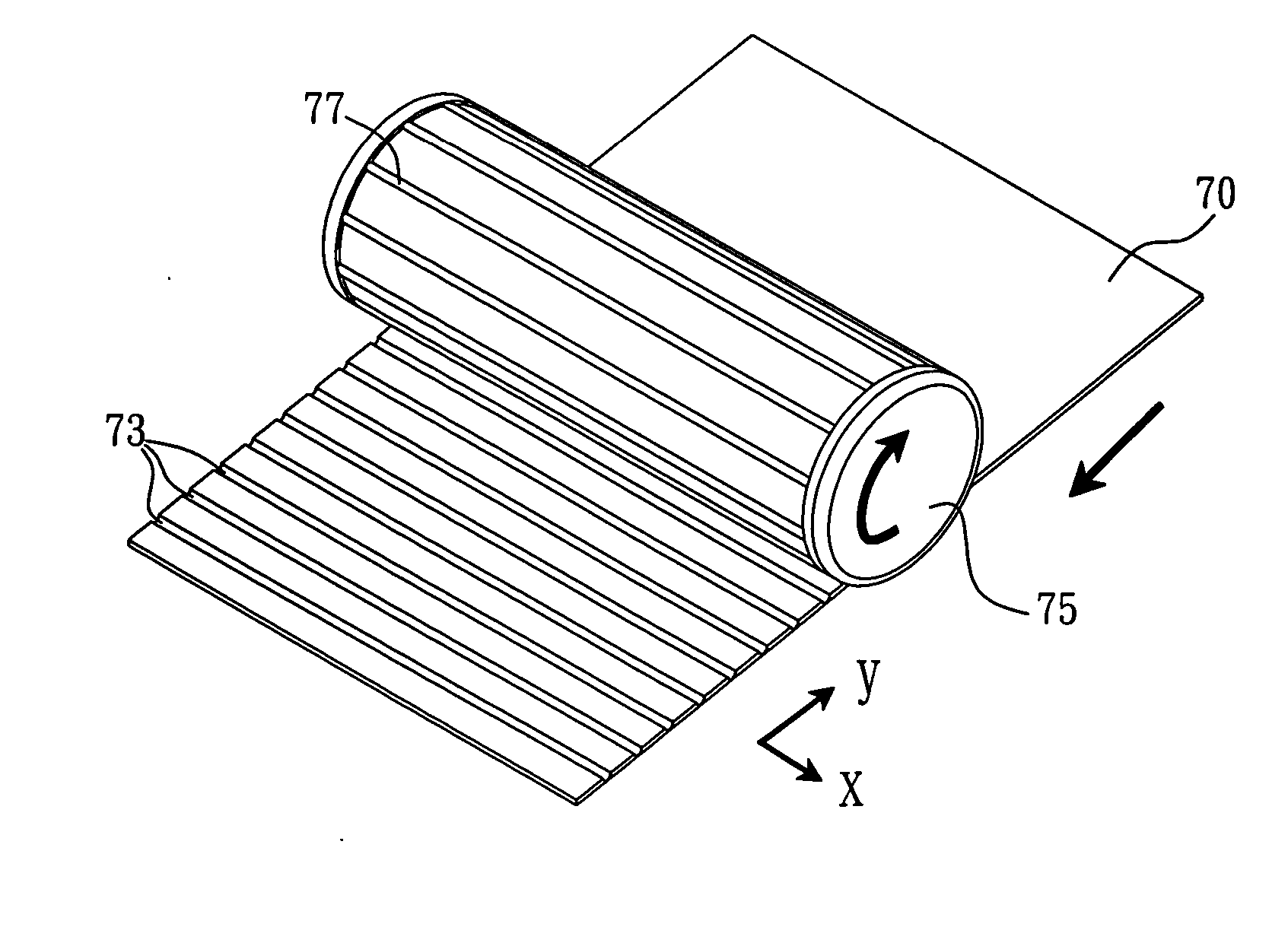
[0022] The present invention relates to a method of making a shadow mask for an opposite discharge plasma display panel. The shadow mask is a thin metal slab 40 as shown in FIG. 6 before the shadow mask is manufactured, and both lateral surfaces of the metal slab 40 are flat and even. The method of the present invention adopts an etching process to etch a plurality of parallel and equidistant barrier ribs 422 along the vertical direction and horizontal direction on a lateral surface of the metal slab 40, wherein a space is formed by enclosing every four adjacent barrier ribs 422 to produce a discharging cell 43 of the opposite discharge plasma display panel, and a shadow hole 41 is etched at the middle of each discharging cell 43 and penetrated through the metal slab 40. A groove 44 is produced on another lateral surface of the metal slab 40 and at a position corresponding to the shadow hole 41 of each discharging cell 43 by a machining process instead of a traditional etching proce...


PUM

PropertyMeasurementUnit
voltageaaaaaaaaaa
transparentaaaaaaaaaa
luminescence efficiencyaaaaaaaaaa

Abstract

The present invention is to provide a method for making a shadow mask for an opposed discharge plasma display panel by etching one lateral surface of a metal slab to produce a plurality of parallel and equidistant barrier ribs along the vertical and horizontal directions on the lateral surface and a discharging cell by enclosing every four adjacent barrier ribs. A shadow hole is formed at the middle of each discharging cell and etched through the metal slab, and at least one groove interconnected to the shadow holes is produced on another lateral surface of the metal slab by utilizing a rolling process or a stamping process. The adjacent grooves are interconnected with each other, and a plurality of air guide channels is formed on another lateral side, such that a shadow mask can be made in a simple and fast manner, chemical pollutions caused by a traditional double-sided etching can be minimized, and the product yield rate and the manufacturing cost can be effectively improved and lowered.

Description

FIELD OF THE INVENTION [0001] The present invention relates to a method for making a shadow mask for an opposed discharge plasma display panel, and more particularly to a method for making a shadow mask for an opposed discharge plasma display panel by utilizing a machining process, instead of a traditional double-sided etching process, to form a plurality of air guide channels in a simple and fast way on one side of the shadow mask needed for manufacturing the opposed discharge plasma display panel. BACKGROUND OF THE INVENTION [0002] Referring to FIG. 1 for the manufacturing technology of a traditional opposite discharge AC type (AC) plasma display panel (PDP) 10, different functional layers are formed on two glass substrates 11, 12, and the peripheries of the two glass substrates are sealed o form a space between the two glass substrates, and a special gas mixed according to a specific proportion such as helium (He), neon (Ne), xenon (Xe) or argon (Ar), etc is filled in the dischar...

Claims


Application Information

Patent Timeline
Patent Type & Authority Applications(United States)
IPC IPC(8): H01L21/00
CPCH01J9/242H01J11/12H01J11/36
Inventor KAO, HSU-PINLIANG, JANG-JENGHSU, SHENG-WENKAO, HSU-CHIA
Owner MARKETECH INT
Why Eureka
Try Eureka