Microcircuit cooling for vanes
- Summary
- Abstract
- Description
- Claims
- Application Information
AI Technical Summary
Benefits of technology
Problems solved by technology
Method used
Image
Examples
Embodiment Construction
)
[0018] The present invention relates to an internal cooling microcircuit positioned within the airfoil portion of a turbine engine component such as a turbine vane.
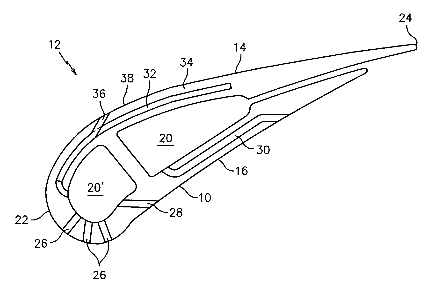
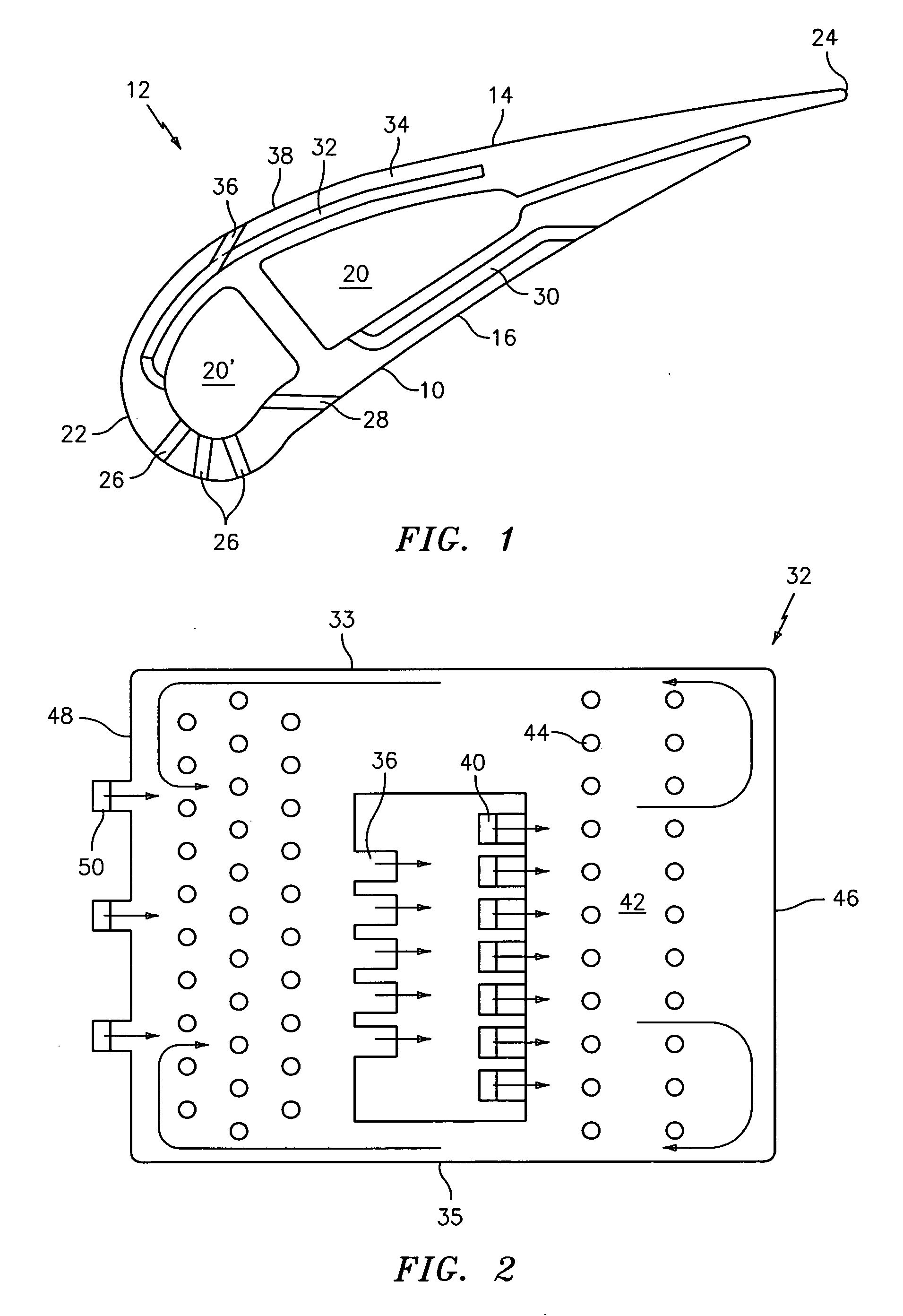
[0019]FIG. 1 illustrates an airfoil portion 10 of a turbine engine component 12 such as a turbine vane. The airfoil portion 10 has a suction side 14 and a pressure side 16. The airfoil portion 10 also may have one or more core elements 20 and 20′ through which cooling fluid may flow. Each core element 20 and 20′ may communicate with a source (not shown) of a cooling fluid such as engine bleed air. The airfoil portion 10 has a leading edge 22 and a trailing edge 24.
[0020] The airfoil portion 10 may have a number of passageways for cooling various portions of its exterior surface. For example, the airfoil portion 10 may have one or more leading edge cooling passageways 26 and 28 which are in fluid communication with the core element 20′. The airfoil portion 10 may also have a cooling passageway 30 for causing cooling flu...
PUM
| Property | Measurement | Unit |
|---|---|---|
| Time | aaaaa | aaaaa |
| Flow rate | aaaaa | aaaaa |
| Velocity | aaaaa | aaaaa |
Abstract
Description
Claims
Application Information
 - R&D
- Intellectual Property
- Life Sciences
- Materials
- Tech Scout
- Unparalleled Data Quality
- Higher Quality Content
- 60% Fewer Hallucinations
Browse by: Latest US Patents, China's latest patents, Technical Efficacy Thesaurus, Application Domain, Technology Topic, Popular Technical Reports.
© 2025 PatSnap. All rights reserved.Legal|Privacy policy|Modern Slavery Act Transparency Statement|Sitemap|About US| Contact US: help@patsnap.com


