
Control apparatus for automotive alternator having capability of reliably detecting disconnection between alternator and battery

a control apparatus and alternator technology, applied in the direction of electric generator control, dynamo-electric converter control, transportation and packaging, etc., can solve the problems of difficult to reliably detect the disconnection, the control apparatus cannot be applied to cases, and the control apparatus and thus the entire electric power generation system become not only complex, but also expensive, and achieve the effect of reliably detecting the disconnection between the alternator and the battery

Active Publication Date: 2007-05-24
DENSO CORP
View PDF9 Cites 27 Cited by
  • Summary
  • Abstract
  • Description
  • Claims
  • Application Information

AI Technical Summary

Benefits of technology

[0020] With the above configuration, it is possible for the control apparatus to reliably detect the disconnection between the alternator and the battery while overcoming the above-mentioned problems accompanying the prior art control apparatuses.
[0026] With the above configuration, it is possible for the control apparatus to reliably detect the disconnection between the alternator and the battery while overcoming the above-mentioned problems accompanying the prior art control apparatuses.
[0031] With the above configuration, it is possible for the electric power generation system to reliably detect the disconnection between the alternator and the battery while overcoming the above-mentioned problems accompanying the prior art control apparatuses.
[0036] With the above configuration, it is possible for the electric power generation system to reliably detect the disconnection between the alternator and the battery while overcoming the above-mentioned problems accompanying the prior art control apparatuses.

Problems solved by technology

Consequently, the control apparatus and thus the entire electric power generation system become not only complex but also expensive.
Consequently, it becomes difficult to reliably detect the disconnection.
Thus, the control apparatus cannot be applied to cases where the alarm lamp is supplied with electric power from a power source other than the battery.

Method used


Image

  • Control apparatus for automotive alternator having capability of reliably detecting disconnection between alternator and battery
  • Control apparatus for automotive alternator having capability of reliably detecting disconnection between alternator and battery
  • Control apparatus for automotive alternator having capability of reliably detecting disconnection between alternator and battery

Examples


first embodiment

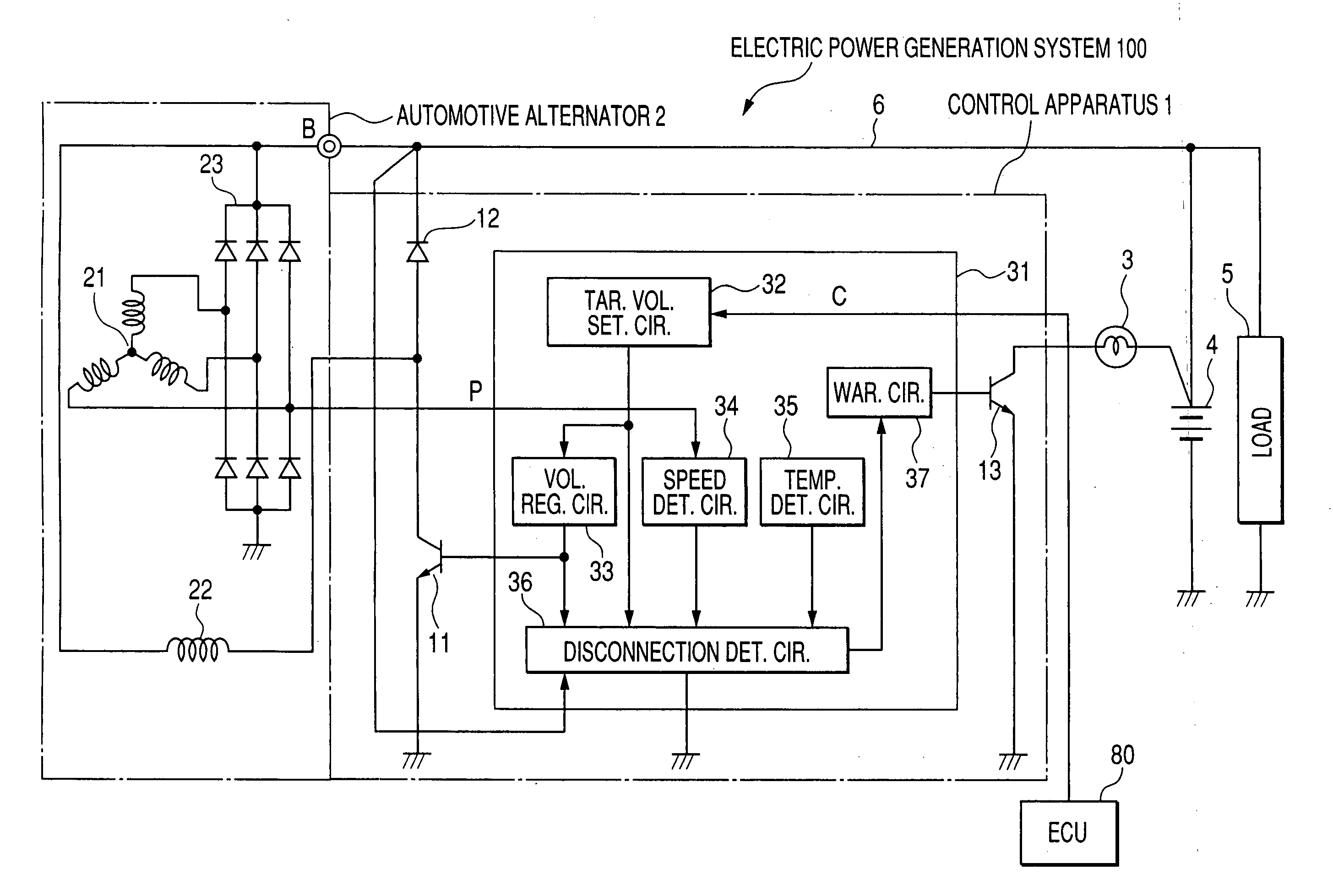
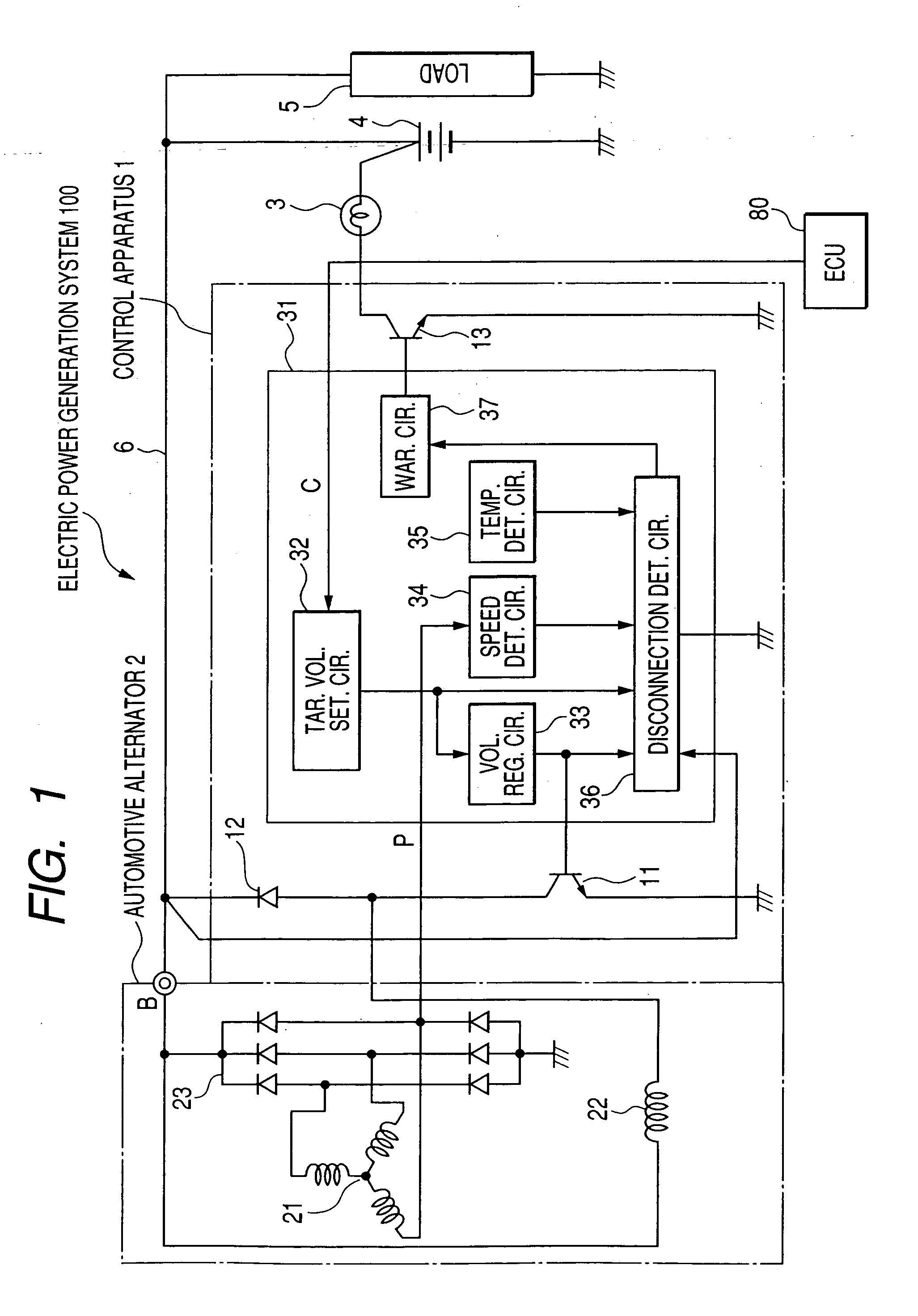
[0046]FIG. 1 shows the overall configuration of an electric power generation system 100 according to the first embodiment of the invention. The electric power generation system 100 is for use in a motor vehicle.

[0047] As shown in FIG. 1, the electric power generation system 100 includes a control apparatus 1, an automotive alternator 2, and an ECU (Electrical Control Unit) 80.

[0048] The alternator 2 includes a three-phase stator winding 21, a field winding 22, and a rectification circuit 23. The stator winding 21 and the filed winding 22 are respectively included in a stator and a rotor of the alternator 2. The rectification circuit 23 is configured to full-wave rectify the three-phase AC output of the stator winding 21 into a DC power.

[0049] The alternator 2 also includes an output terminal B that is electrically connected to a battery 4 and electrical load 5 via a conducting wire 6, so that the battery 4 and the electrical load 5 can be supplied with the DC power necessary for ...

second embodiment

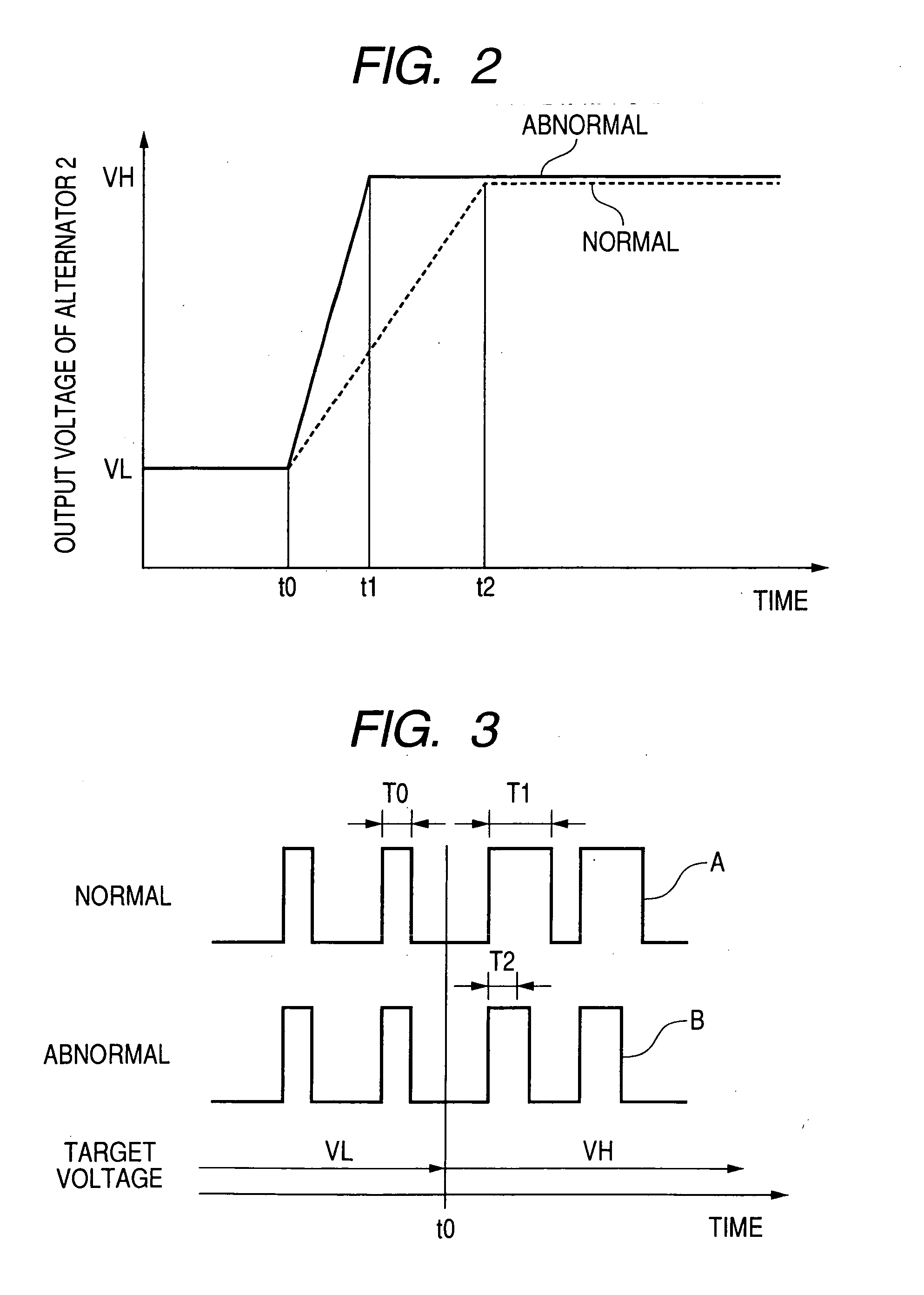
[0071]FIG. 3 illustrates the basic principle of a disconnection detection process of the control apparatus 1 according to the present embodiment, which is different from the disconnection detection process according to the previous embodiment.

[0072] Suppose that the target voltage of the alternator 2 is changed from the lower value VL to the higher value VH at a time instant t0.

[0073] Then, under normal conditions, the on-time of the field transistor 11 considerably increases from T0 to T1, as indicated by a pulse A in FIG. 3, due to the battery 4 and the electrical load 5 connected to the alternator 2. In other words, the difference in duty cycle of the field transistor 11 between after and before the change in the target voltage is large.

[0074] In comparison, under abnormal conditions, the on-time of the field transistor 11 slightly increases from T0 to T2, as indicated by a pulse B in FIG. 3, due to the no-load running of the alternator 2. In other words, the difference in dut...

third embodiment

[0078] This embodiment illustrates an electric power generation system 100A which has a configuration similar to that of the electric power generation system 100 according to the first embodiment. Accordingly, only the differences therebetween will be described hereinafter.

[0079] Referring to FIG. 4, the electric power generation system 100A according to the present embodiment includes a control apparatus 1A, an automotive alternator 2, and an ECU 80A.

[0080] The control apparatus 1A includes a field transistor 11, a freewheeling diode 12, and a control circuit 31A.

[0081] The control circuit 31A includes a target voltage setting circuit 32, a voltage regulating circuit 33, a warning circuit 37A, and a duty-cycle signal transmitting circuit 38.

[0082] The warning circuit 37A works to activate the warning transistor 13 to light the warning lamp 3 when the electric power generation system 100A is in a fault condition other than the disconnection between the alternator 2 and the batte...


PUM


Abstract

According to the present invention, there is provided a control apparatus for an automotive alternator which includes a switch, a target voltage setter, a voltage regulator, and a disconnection detector. The switch is configured to be selectively turned on and off so as to intermittently excite the alternator. The target voltage setter works to set a target voltage. The voltage regulator works to regulate an output voltage of the alternator to the target voltage through controlling on / off operation the switch. The disconnection detector works to detect disconnection between the alternator and an on-board battery to be charged by the alternator. The disconnection detector is configured to detect the disconnection, when the target voltage is changed from a lower value to a higher value, based on a time required for the voltage regulator to bring the output voltage of the alternator from the lower value to the higher value.

Description

CROSS-REFERENCE TO RELATED APPLICATION [0001] This application is based on and claims priority from Japanese Patent Application No. 2005-335061, filed on Nov. 18, 2005, the content of which is hereby incorporated by reference into this application. BACKGROUND OF THE INVENTION [0002] 1. Technical Field of the Invention [0003] The present invention relates generally to control apparatuses for automotive alternators and electric power generation systems for vehicles. More particularly, the invention relates to a control apparatus for an automotive alternator which has a capability of reliably detecting disconnection between the alternator and an on-board battery to be charged by the alternator. [0004] The disconnection includes a state where a conducting wire electrically connecting the alternator and the battery is broken and a state where the conducting wire is detached from at least one of terminals of the alternator and the battery. This definition will be applied to all the descri...

Claims


Application Information

Patent Timeline
Patent Type & Authority Applications(United States)
IPC IPC(8): H02H7/06H02P9/00H02P11/00
CPCH02J7/1461H02J7/244H02P2101/45Y02T10/7005H02P9/006H02J7/243Y02T10/70H02J7/0047
Inventor INOKUCHI, TAKATOSHITSUZUKI, TOMOMIASADA, TADATOSHI
Owner DENSO CORP
Learn More