
Fluid ultraviolet sterilization system

a sterilization system and fluorescence technology, applied in the field of fluorescence ultraviolet sterilization system, can solve the problems of increasing construction and land costs, affecting the overall sterilization effect, and reducing so as to improve the sterilization effect, reduce the area occupied by the system, and reduce the effect of the operating reliability and safety of the sterilization system

Inactive Publication Date: 2007-05-24
FUJIAN NEWLAND ENTECH CO LTD
View PDF5 Cites 9 Cited by
  • Summary
  • Abstract
  • Description
  • Claims
  • Application Information

AI Technical Summary

Benefits of technology

[0006] Therefore, the object of this invention is to provide a fluid UV sterilization system with a simple structure and occupying less area, which allows for a large variation range of flow rate, and can keep the fluid level automatically and operate reliably.

Problems solved by technology

When the flow rate of the fluid increases such that the fluid level goes beyond the effective radiation distance of the UV sterilization system (said effective radiation distance means the largest distance between a UV light source and viruses or bacteria that can be annihilated or deactivated by the UV light source in the fluid to be sterilized, with the fluid to be sterilized having a certain transmissivity), part of the fluid will be drained away directly without being effectively sterilized, thus impairing the overall sterilization effect.
Therefore, the channel has to be considerably lengthened and the cost for construction and land has to be increased, and the drainage of fluid is also disadvantageously influenced.
Similarly, in this case the highest fluid level in the sterilization area should not go beyond the effective radiation distance of the UV lamp module(s), otherwise, part of the fluid which is beyond the effective radiation distance would flow out of the channel without receiving sufficient UV radiation, thus impairing the overall sterilization effect.
In this system it is not possible to ensure that all the fluid in the channel would pass through the effective radiation area and receive sufficient UV radiation when the flow rate or the variation range of the flow rate is large.
Furthermore, since there are a large number of devices in the system, the cost is increased, and the convenience for assembly and maintenance as well as the operating reliability are impaired.

Method used


Image

  • Fluid ultraviolet sterilization system
  • Fluid ultraviolet sterilization system
  • Fluid ultraviolet sterilization system

Examples


first embodiment

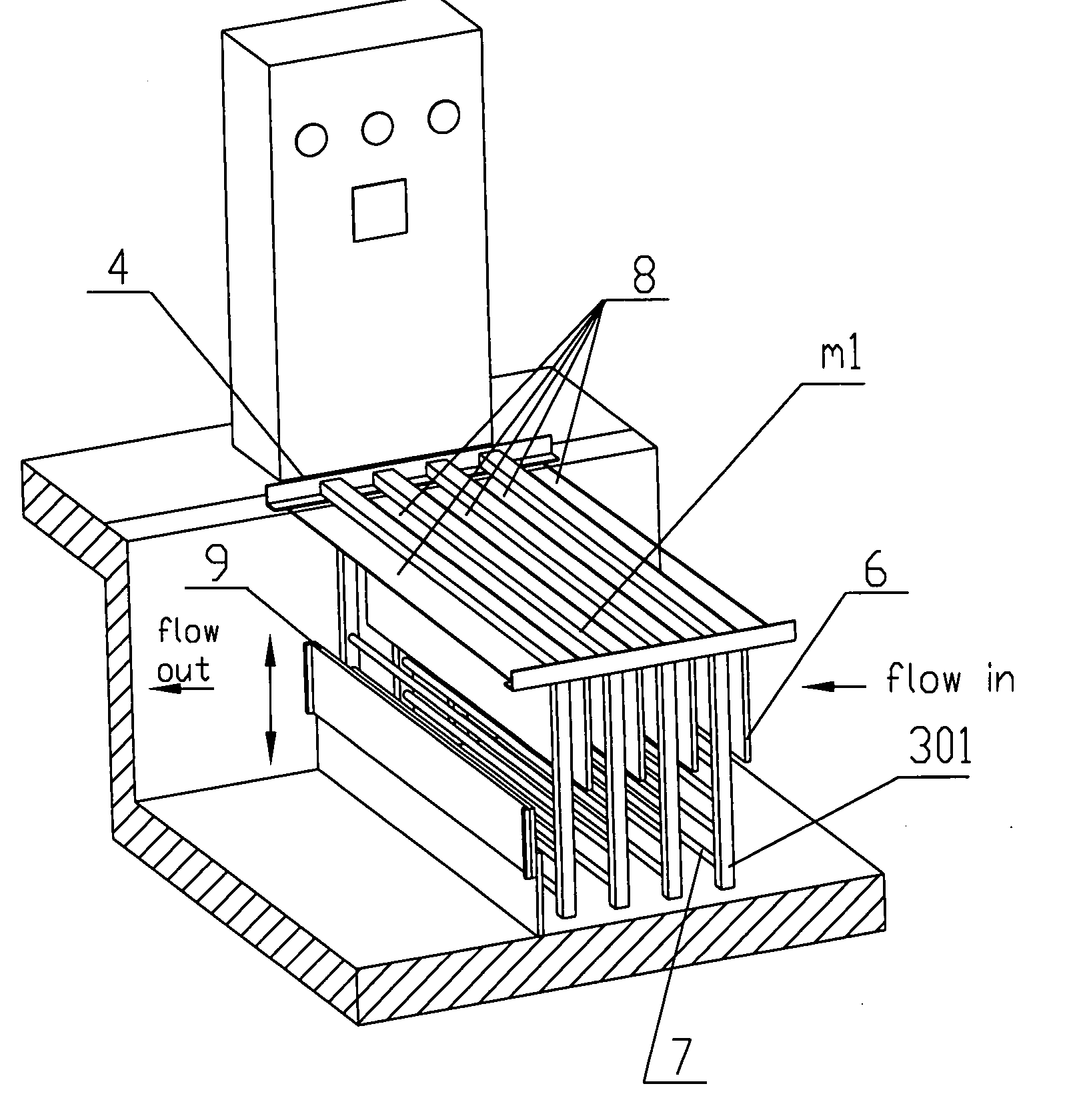
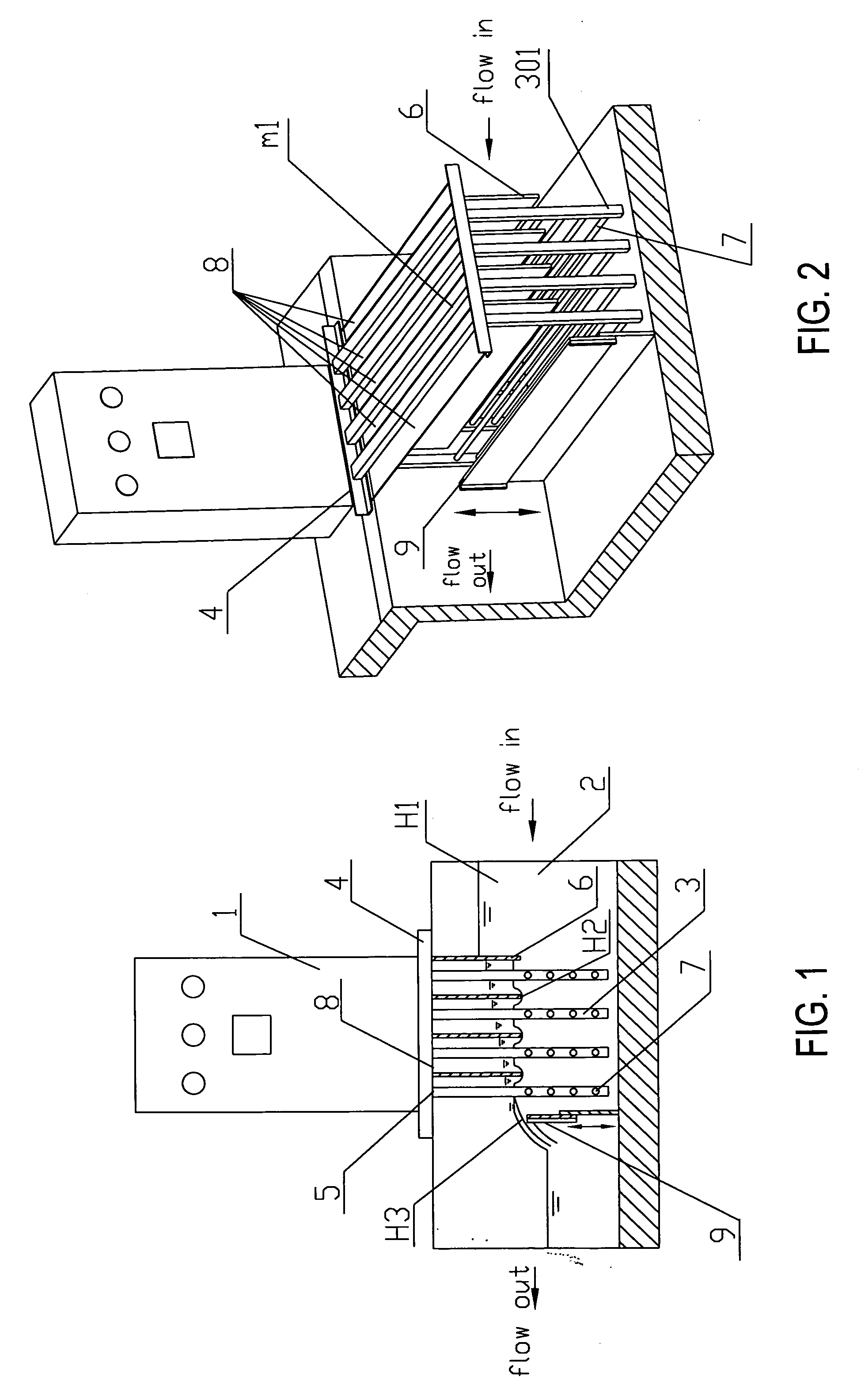
[0026] In the invention, as shown in FIG. 1 and FIG. 2, the fluid to be sterilized flows into the channel 2 from one end thereof, and the other end of the channel 2 is provided with a fluid level control device 9 for fluid outflow. The fluid UV sterilization system includes one UV lamp module group m1, which consists of a plurality of UV lamp modules 3, and each of the UV lamp modules 3 comprises a frame 301 and a plurality of UV lamps 7 mounted on the frame and arranged parallel to each other. The orientation of the frame of each of the UV lamp modules is perpendicular to the general flow direction in the channel.

[0027] The mounting bracket 4 for the UV lamp module group is fixed on the channel. The mounting bracket 4 is provided with exactly the same number of mounting slots 5 as that of the UV lamp modules for the mounting of the latter. A closed light-shielding plate 8 is provided between adjacent mounting slots 5 of the mounting bracket 4 for shielding the UV light from leaking...

third embodiment

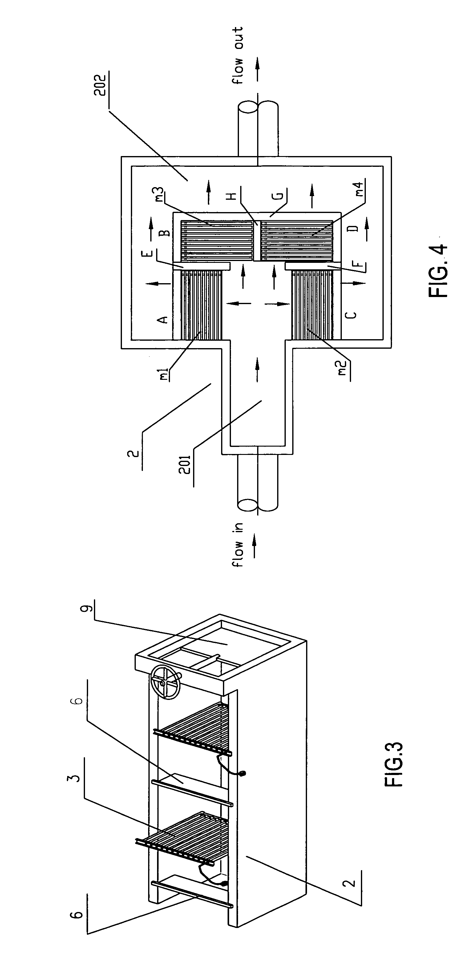
[0032] In the invention, as shown in FIG. 4, four UV lamp module groups m1, m2, m3, m4 are respectively parallel to or perpendicular to the general flow direction in the channel. In this embodiment the fluid level control device is used as an overflow weir at the outlet end of the channel, such that the sterilized fluid overflows out naturally. As shown in FIG. 4, the fluid inlet end and the fluid outlet end of the channel 2 are respectively designated by 201 and 202. The walls B and D are both higher than the fluid level in the channel to prevent the fluid from overflowing from the top of the walls B and D. The walls A, C and G are used as outflow weirs 9, and the walls E, F and H are used for mounting the mounting brackets for the UV lamp modules. The walls A, B, C, D, E, F, G and H are all in sealingly contact with the bottom of the channel.

[0033] The arrows in FIG. 4 represent the flow directions of the fluid. As described in the first embodiment, one baffle can be provided on t...


PUM

PropertyMeasurementUnit
radiation distanceaaaaaaaaaa
widthaaaaaaaaaa
thicknessaaaaaaaaaa

Abstract

The invention provides a fluid UV sterilization system capable of automatically and stably keeping the fluid level, which includes a channel, a UV lamp module group, an electrical controller and a mounting bracket for UV lamp module(s), each UV lamp module comprising a frame and a plurality of UV lamps, the orientation of the frame and the lamps is perpendicular to or forms an angle with the general flow direction in the channel. A baffle is provided on either or both of the upstream and downstream of at least one of the UV lamp module(s), and the bottom of the baffle extends to such an extent towards the bottom of the channel that it at least reaches within the effective radiation distance of the UV lamp module group towards the fluid surface. The fluid UV sterilization system according to the present invention can control the fluid level automatically and stably, and can be used for the sterilization of domestic sewage, industrial sewage, recycled water, tap water and other kinds of water.

Description

FIELD OF THE INVENTION [0001] The invention relates to fluid ultraviolet (UV) sterilization, and more particularly to a fluid UV sterilization system capable of keeping the fluid level automatically. DESCRIPTION OF RELATED ART [0002] It is well known that a fluid UV sterilization system requires keeping a certain fluid level so as to ensure the sterilization effect. When the flow rate of the fluid increases such that the fluid level goes beyond the effective radiation distance of the UV sterilization system (said effective radiation distance means the largest distance between a UV light source and viruses or bacteria that can be annihilated or deactivated by the UV light source in the fluid to be sterilized, with the fluid to be sterilized having a certain transmissivity), part of the fluid will be drained away directly without being effectively sterilized, thus impairing the overall sterilization effect. Therefore, it is necessary to control the fluid level or the flow rate of the ...

Claims


Application Information

Patent Timeline
Patent Type & Authority Applications(United States)
IPC IPC(8): G01N23/00
CPCC02F1/325C02F2201/004C02F2201/3225C02F2201/328C02F2209/42
Inventor CHEN, JIANHAN, MINYI
Owner FUJIAN NEWLAND ENTECH CO LTD
Learn More