
Endoluminal device and system and method for detecting a change in pressure differential across an endoluminal device

a technology of endoluminal devices and pressure differentials, which is applied in the field of endoluminal devices, can solve the problems of endoleakage, ruptured aneurysms, and patient death, and achieve the effects of reducing the risk of endoleakag

Inactive Publication Date: 2007-05-17
LIFESHIELD SCI
View PDF12 Cites 13 Cited by
  • Summary
  • Abstract
  • Description
  • Claims
  • Application Information

AI Technical Summary

Benefits of technology

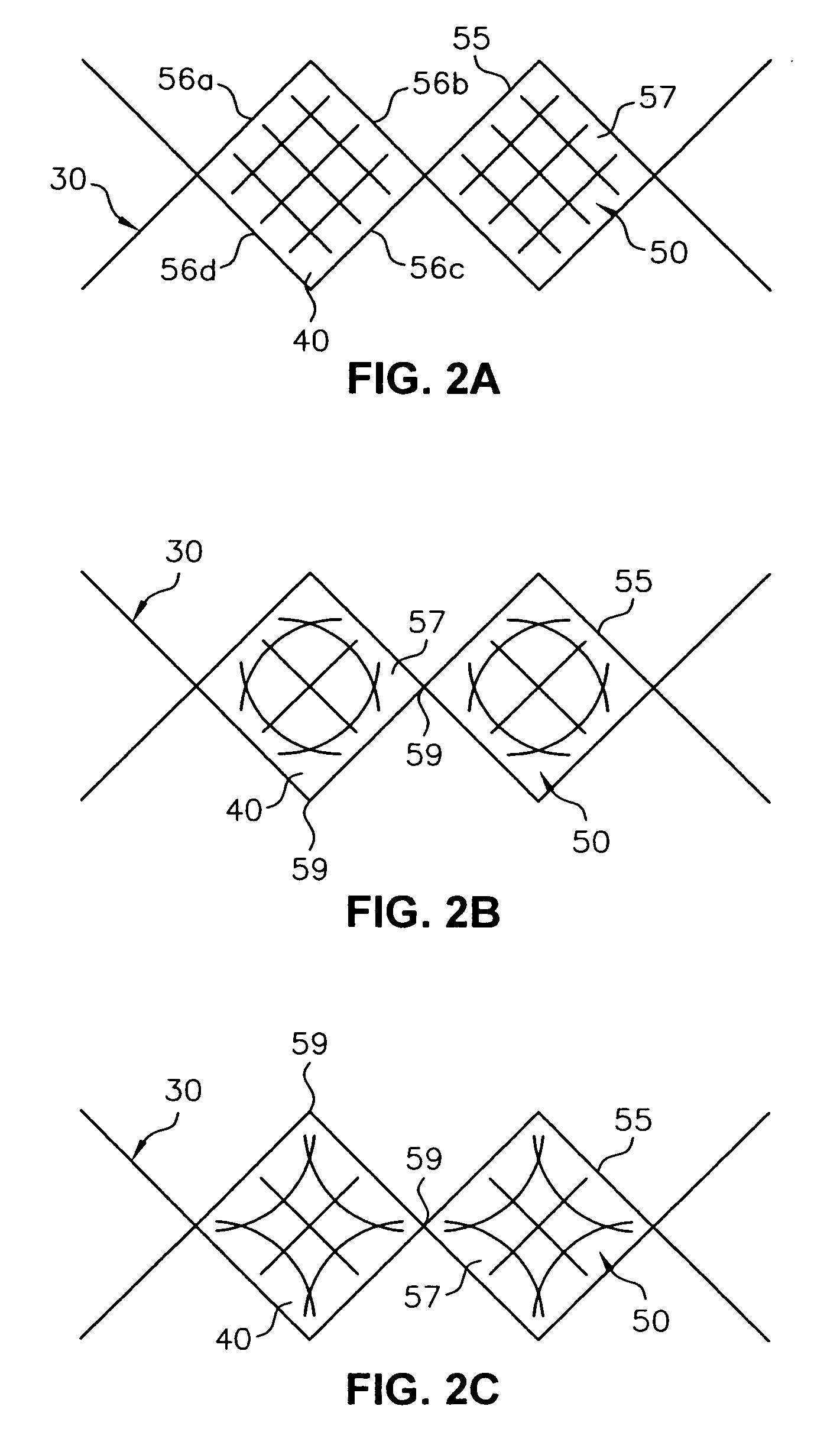
"The present invention provides an endoluminal device for deployment in a body lumen that includes a radially expandable stent, a graft attached to the stent, and a plurality of indicator members affixed to the graft. The indicator members are adapted to form a normal pattern in response to a normal pressure differential between the internal pressure and the external pressure, and an abnormal pattern in response to an abnormal pressure differential between the internal pressure and the external pressure. The invention also provides a system for detecting a change in pressure differential across the device and a method for detecting a change in pressure differential across the device."

Problems solved by technology

After the aneurysm has been isolated for some time, endoleaks may occur due to worn fabric or other reasons.
Because the isolated aneurysm may become weak as a result of being isolated, once the leak starts, blood flow and pressure is slowly restored to the aneurysm, and the aneurysm may rupture.
Currently, leaks are detected during follow-up angiograms and MRIs, but if the follow up visit does not coincide with the duration of time within which the leak must be treated, the undetected endoleak may result in a ruptured aneurysm that can be fatal to the patient.
The pressure measurement is taken relative to atmospheric pressure, so that the precision of the measurement is compromised by the need to operate over a range of absolute pressure from atmospheric up to systole.

Method used


Image

  • Endoluminal device and system and method for detecting a change in pressure differential across an endoluminal device
  • Endoluminal device and system and method for detecting a change in pressure differential across an endoluminal device
  • Endoluminal device and system and method for detecting a change in pressure differential across an endoluminal device

Examples


Embodiment Construction

[0016] The invention will next be illustrated with reference to the figures wherein similar numbers indicate the same elements in all figures. Such figures are intended to be illustrative rather than limiting and are included herewith to facilitate the explanation of the apparatus of the present invention.

[0017]FIG. 1 shows a partial cross-section of an endoluminal device 20 according to the present invention. Endoluminal device 20 can be implanted in a body lumen 100 in an area of an aneurysm 102. As shown, body lumen 100 is the aorta which branches into iliac arteries 101a and 101b; thus, in the embodiment shown in FIG. 1, endoluminal device 20 is a bifurcated endoluminal device, although the present invention contemplates the use of other types of endoluminal devices or prostheses in other body lumen.

[0018] The device includes a radially expandable stent 30, a graft 40 attached to the stent, plurality of indicator members 50 affixed to the graft. The configuration of the indica...


PUM


Abstract

An endoluminal device for deployment in a body lumen includes a radially expandable stent, a graft attached to the stent, and a plurality of indicator members affixed to the graft and adapted to form a normal pattern in response to a normal pressure differential and an abnormal pattern in response to an abnormal pressure differential across the graft. By forming different patterns at different pressure differentials, the indicator members enable the detection of a change in pressure which could be evidence of a leak. A system for detecting a change in pressure differential includes the endoluminal device and an imaging system for displaying the indicator members. A method for detecting a change in pressure includes the steps of identifying the normal pattern, implanting the device, imaging the indicator members, and comparing the imaged pattern with the normal pattern to determine whether the normal pressure or an abnormal pressure differential exists.

Description

CROSS REFERENCE TO RELATED APPLICATIONS [0001] This is a Continuation Application of allowed U.S. patent application Ser. No. 10 / 143,434 filed on May 10, 2002.TECHNICAL FIELD [0002] This invention relates generally to endoluminal devices and, more specifically, to the detection of changes in pressure differential across such devices and the detection of leaks after implantation of such devices. BACKGROUND OF THE INVENTION [0003] An endoluminal device or prosthesis typically includes a stent and a fabric layer, or graft, supported by the stent. A stent is an elongated device which serves to affix the prosthesis in place by providing a radial force against a lumen wall, in addition to supporting the graft. The graft is typically made of a fabric or textile which has a low permeability with respect to the fluid, such as blood, flowing within the prosthesis. The graft may be fully supported by the stent along the entire length of the graft. Alternatively, the graft may have regions whic...

Claims


Application Information

Patent Timeline
Patent Type & Authority Applications(United States)
IPC IPC(8): A61F2/06A61B5/0215A61F2/00
CPCA61B5/0215A61F2/07A61F2002/075A61F2250/0097A61F2250/0013
Inventor SMITH, JOHN K.
Owner LIFESHIELD SCI
Learn More