
Method of operating fuel cell

Inactive Publication Date: 2007-05-10
AISIN SEIKI KK
View PDF0 Cites 4 Cited by
  • Summary
  • Abstract
  • Description
  • Claims
  • Application Information

AI Technical Summary

Benefits of technology

[0026] Where the performance of the fuel cell is degraded, the deterioration of the cathode can be recovered, and conseq

Problems solved by technology

With these methods, however, a long period of time is required, and only one reason for the degradation of the performance is merely removed.
Accordingly, it is doubtful whether the characteristic ability of the fuel cell can be entirely effected merely with the above-described techniques of the patent documents.

Method used


Image

  • Method of operating fuel cell
  • Method of operating fuel cell
  • Method of operating fuel cell

Examples


embodiment 2

(Embodiment 2)

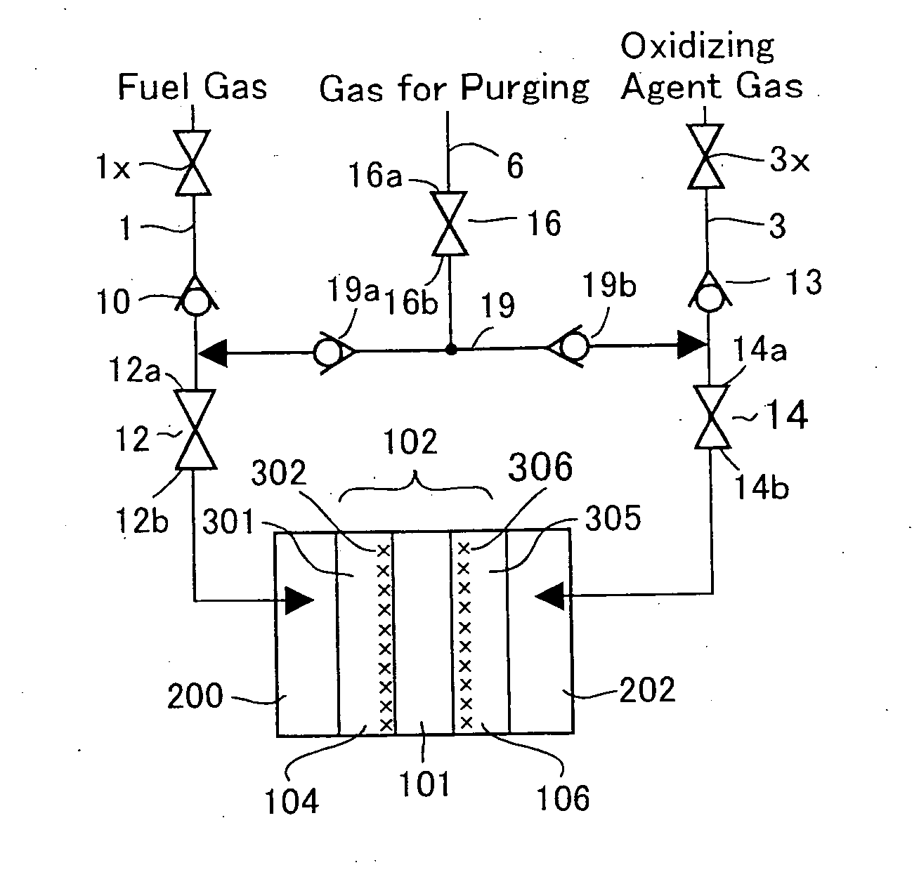
[0064] A fuel cell module 100 (see FIG. 5) was prepared by assembling a plurality of single cells, each being composed of the membrane electrode assembly 102 prepared in the embodiment 1. In the embodiment 2, the cell voltage was determined to 0.05 volt under basically similar conditions to those of the embodiment 1, and after the fuel cell module 100 was discharged with a constant voltage for five minutes, a normal power generation experiment was carried out with 0.38 ampere / cm2. Power was generated by feeding air (utilization factor: 40%) as an oxidizing agent gas to the cathode 106 of the fuel cell module 100, and feeding a pure hydrogen gas (utilization factor: 90%) as fuel to the anode 104 of the fuel cell module 100. After 10 hours, the power generation by the fuel cell module 100 was stopped. And nitrogen was fed only to the anode 104 to purge the anode 104 with nitrogen. Then, the fuel cell module 100 was turned to invert two sides thereof. As a result, as show...

embodiment 3

(Embodiment 3)

[0069] A single cell was composed of the membrane electrode assembly 102 prepared in the embodiment 1. In the embodiment 3, under basically similar conditions to those of the embodiment 1, namely, at a cell temperature of 75° C., air (utilization factor: 40%) as an oxidizing agent gas was fed to the cathode 106 under a normal pressure, and a pure hydrogen gas (utilization factor: 90%) as a fuel gas was fed to the anode 104 under a normal pressure. And the cell voltage was determined to 0.05 volt, and after the cell was discharged with a constant potential for five minutes, a normal power generation experiment was carried out with 0.38 ampere / cm2. After 10 hours, the power generation was stopped. And only the anode 104 was purged with nitrogen and the power generating step was finished. After finished, the cell was left quiet for 10 hours, nitrogen gas as a gas for purging was fed to the cathode 106, thereby carrying out the nitrogen purge. Then, the feeding of gas was ...


PUM


Abstract

A method for operating a fuel cell, which is capable of recovering the performance of the fuel cell when the performance of the fuel cell is degraded. The fuel cell includes a membrane electrode assembly having an electrolyte film, an anode, and a cathode. The anode and the cathode sandwich the electrolyte film and carry a catalyst metal. An oxidizing agent is fed to the cathode and fuel is fed to the anode to generate power. After a predetermined period of time has passed, two sides of the membrane electrode assembly are inverted to carry out a changing operation of changing the anode before inverted to a cathode, and changing the cathode before inverted to an anode. After the changing operation, an oxidizing agent is fed to the cathode after changed and fuel is fed to the anode after changed, thereby starting a power generation again.

Description

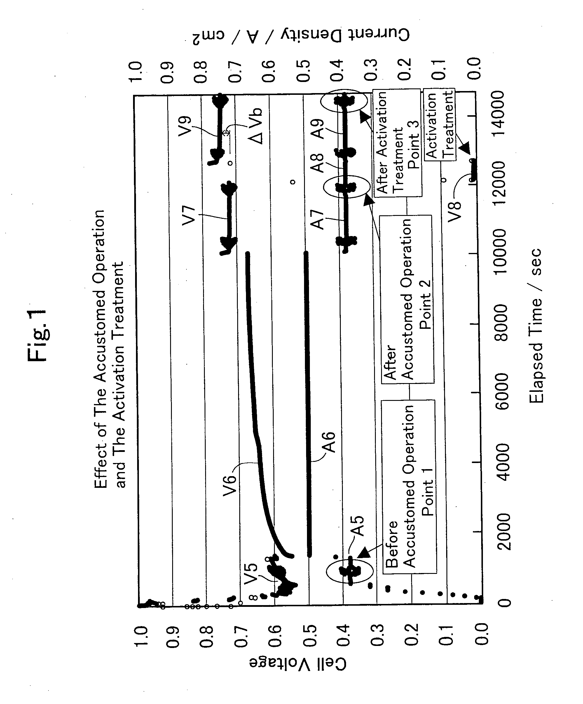
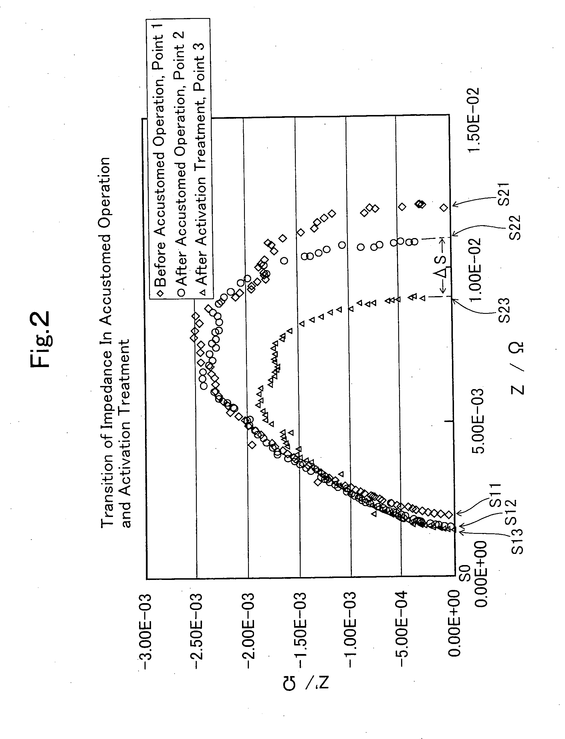
TECHNICAL FIELD [0001] The present invention relates to a method for operating a fuel cell, which is favorable to keep a high output. BACKGROUND ART [0002] The performance of a fuel cell is gradually degraded with time. Conventionally, before the normal operation of the fuel cell, there has been carried out the method of supplying an electric current with a higher current density than a predetermined current density to enhance the output of the fuel cell, which is called the accustomed operation. The accustomed operation intends to wet an electrolyte film at the beginning of the operation of the fuel cell. By carrying out the accustomed operation using a pure oxygen gas as an oxidizing agent to be fed to a cathode with a current density as great as possible and for a period as long as possible, the cell voltage can be remarkably enhanced. [0003] However, the above-described accustomed method requires a long operation time and is carried out with a great electric current so that the ...

Claims


Application Information

Patent Timeline
IPC IPC(8): H01M8/00H01M8/10H01M8/04
CPCH01M8/04089H01M8/04223H01M2008/1095Y02E60/50H01M8/04303H01M8/04302H01M8/04225H01M8/04228H01M8/043
Inventor XIE, GANG
Owner AISIN SEIKI KK
Learn More