
Applicators and methods for dispensing a liquid material

a liquid material and application technology, applied in the field of liquid material dispensing, can solve the problems of lack of selectively creating overlapping or non-overlapping patterns of gas impinging filaments, and achieve the effects of increasing the surface area of the discharged, increasing the width, and increasing the surface area of the dispensed filaments

Inactive Publication Date: 2007-05-10
NORDSON CORP
View PDF16 Cites 21 Cited by
  • Summary
  • Abstract
  • Description
  • Claims
  • Application Information

AI Technical Summary

Benefits of technology

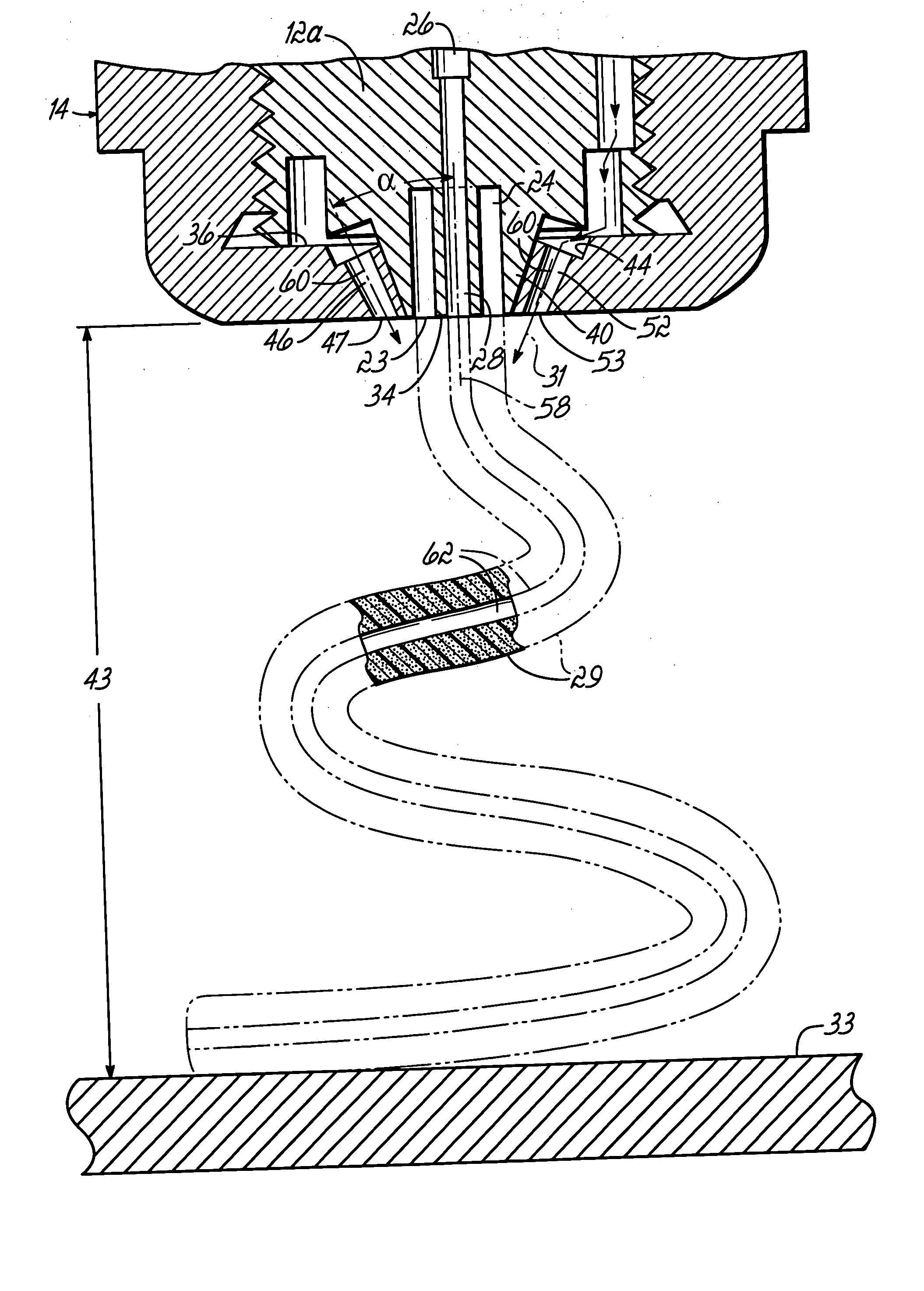
[0073] One advantage of the invention is to effectively increase the surface area of the discharged hollow filaments while retaining the same mass of liquid material per unit length, which conserves the amount of liquid material while permitting a larger width to be covered on the moving substrate. To that end, the surface area of the dispensed filament is increased by making the discharged filament hollow along its length. Hollow filaments have a greater outer diameter and surface area in comparison with a solid filament of comparable mass per unit length. When impinged by gas jets, the increase in the filament surface area may result in greater oscillation frequency and / or greater oscillation amplitude due to the increased momentum transfer from the gas jets to the filament, as compared with a solid core filament.
[0074] Alternatively, the filament may be shaped to include multiple lobes, as opposed to a smoothly curved outer surface. Shaped filaments have plural intersecting arms or lobes (e.g., plus-shaped), which may have a greater surface area, that are impinged by the gas jets to provide surfaces for momentum transfer. When impinged by gas jets, the change in filament shape may result in greater oscillation frequency and / or greater oscillation amplitude due to the increased momentum transfer from the gas jets to the filament, as compared with a solid core filament having a smoothly curved (e.g., cylindrical) cross-sectional profile without lobes or arms. Overlapping or non-overlapping patterns may be ultimately dispensed onto the substrate.
[0075] With reference to FIGS. 12-14 in which like reference numerals refer to like features in FIGS. 1-11 and in accordance with an alternative embodiment of the invention, a liquid material dispenser 110 includes a plurality of arc-shaped or C-shaped liquid material passages 112, 114, 116 that are arranged in a line across a dispenser body 119. Each of the liquid material passages 112, 114, 116 is similar or identical to liquid material passage 74 (FIGS. 8 and 8A). Each of the liquid material passages 112, 114, 116 includes an arc-shaped or C-shaped outlet 113, 115, 117 formed by the intersection of the corresponding one of the liquid material passages 112, 114, 116 with a surface of a frustoconical discharge tip 118, 120, 122, respectively.
[0076] With reference to FIG. 14, liquid material passage 112 includes a discontinuity 124 defined in liquid material outlet 113 between the confronting ends of the C-shape. A plurality of, for example, four gas outlets 126, 128, 130, 132 surround the discharge outlet 113 and are each defined by the intersection of a corresponding one of a plurality of gas passages 136, 138, 140, 142 with an inclined surface 134 that is inclined in a direction toward the discharge tip 118. The liquid material outlet 113 is defined in a generally flat surface 144 at the end of discharge tip 118. Surface 144 is separated from surface 134 so that the liquid material outlet 113 is non-planar with the gas outlets 126, 128, 130, 132.
[0077] The gas outlets 126, 128, 130, 132 direct gas streams generally toward the discharged stream of liquid material and cooperate to transfer momentum to the hollow filament 18 (FIG. 8A) discharged from discharge outlet 113. The gas streams discharged from the gas outlets 126, 128, 130, 132 operate to move and attenuate the discharged stream of the liquid material that defines the hollow filament. The orientation of the gas streams is determined by the inclination angle of the corresponding one of the gas passages 136, 138, 140, 142 relative to the discharge outlet 113.
[0078] The other liquid material outlets 115, 117 are each surrounded by a set of gas outlets similar to gas outlets 126, 128, 130, 132. Consequently, the liquid material dispenser 110 is adapted to dispense a plurality of hollow filaments (FIG. 8A) such that each individual filament contacts the substrate 33 (FIG. 6) with a pattern. A person having ordinary skill in the art will understand the liquid material passages 112, 114, 116 and the liquid material outlets 115, 117, 119 thereof may be configured to have any of the configurations described herein.

Problems solved by technology

The gas impinging these filaments lacks the ability to selectively create overlapping or non-overlapping patterns.

Method used


Image

  • Applicators and methods for dispensing a liquid material
  • Applicators and methods for dispensing a liquid material
  • Applicators and methods for dispensing a liquid material

Examples


example 1

[0083] Hollow filaments of an adhesive were oscillated by a process consistent with the embodiment of the invention described with regard to FIGS. 1-6. The frequency of the oscillating hollow filament after striking the substrate was measured as a function of fiber hollowness. Fiber hollowness was determined from the flow rate of gas injected into the filament center.

[0084] Hollow filaments were formed using an annular liquid material outlet surrounding a coaxial gas discharge outlet and then steered by gas streams by an apparatus similar to dispenser 10 (FIG. 1) to define an oscillating pattern. The filaments were formed from a ZEROPACK® hot melt adhesive commercially available from HB Fuller (St. Paul, Minn.) and using thirteen (13) standard liters per minute (SLM) of non-heated gas discharged for oscillating the filament. The adhesive was discharged at fifty-four (54) grams per minute at a temperature of 150° C. (head & hose) through an annular ring outlet of a dispensing die an...


PUM

PropertyMeasurementUnit
Shapeaaaaaaaaaa
Frequencyaaaaaaaaaa
Perimeteraaaaaaaaaa

Abstract

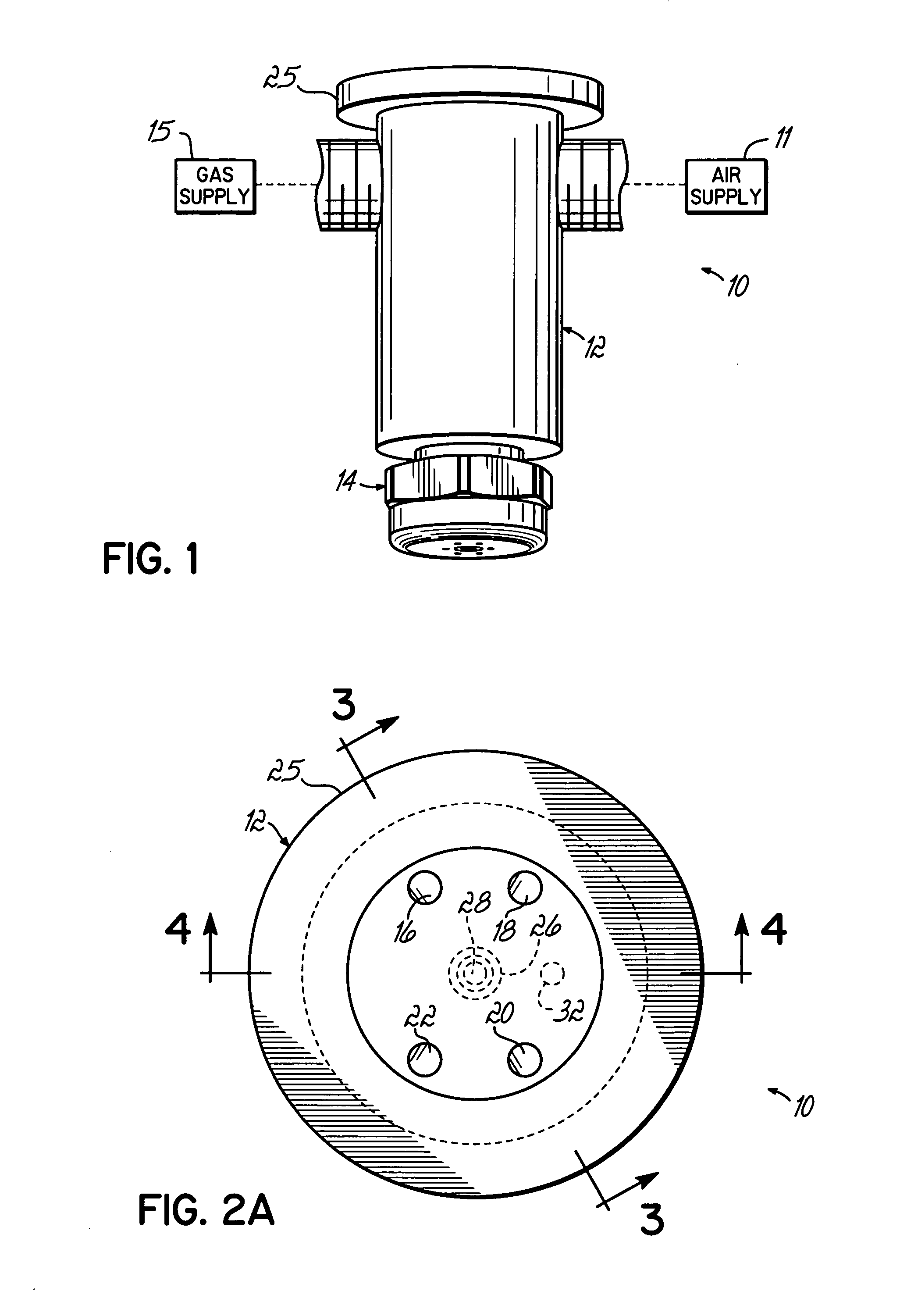
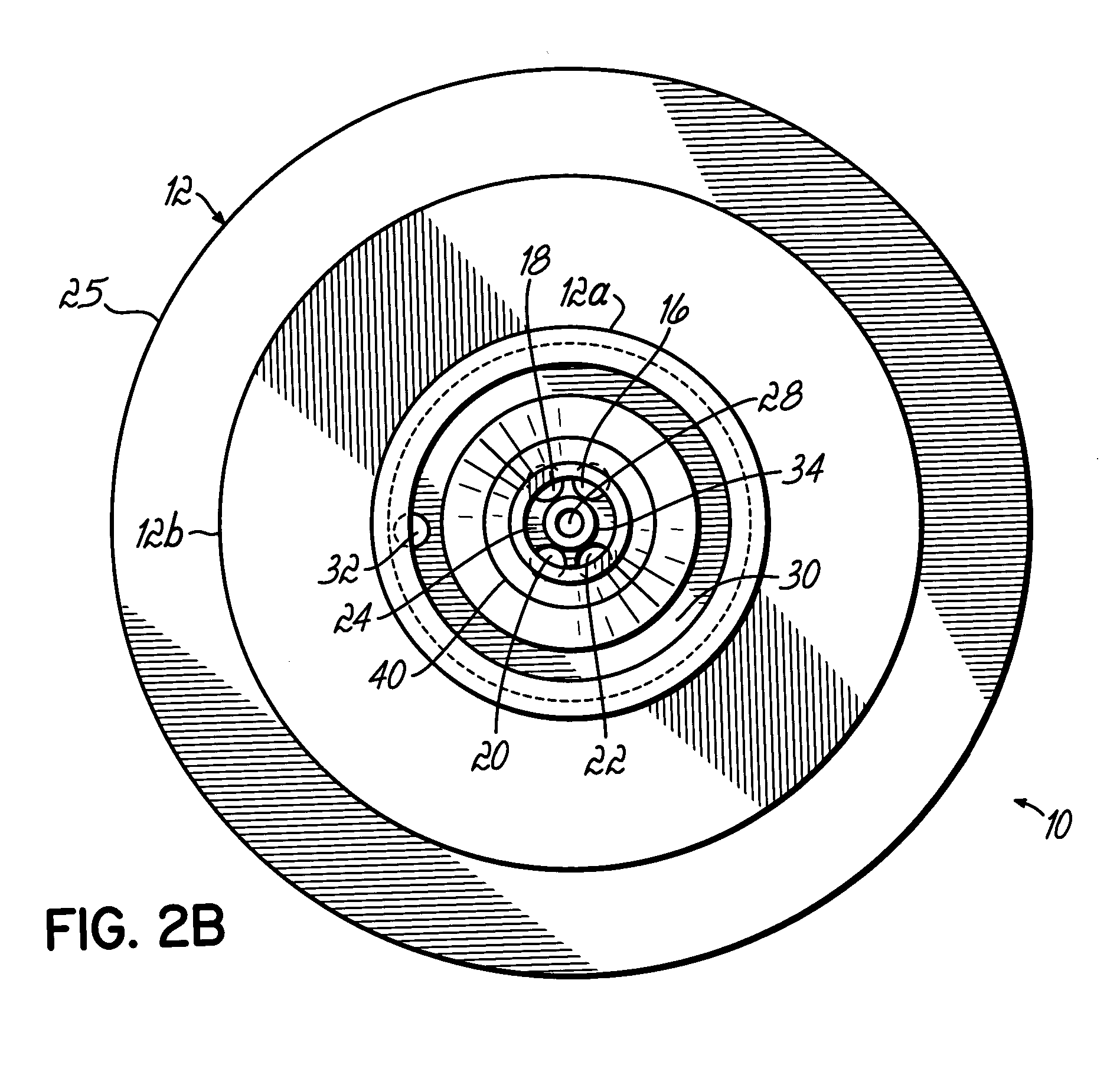
Applicators configured to dispense a hollow or shaped filament and methods of dispensing in which the hollow or shaped filament is impinged with gas jets. The applicator includes a dispenser body configured to discharge the hollow or shaped filament and a plurality of gas outlets arranged to impinge the filament in the space between the dispenser and the substrate.

Description

FIELD OF THE INVENTION [0001] The present invention generally relates to liquid material dispensing and, more particularly, to applicators with gas jets that impinge a dispensed liquid material filament and methods of dispensing liquid material filaments with gas jet impingement. BACKGROUND OF THE INVENTION [0002] Dispensers discharge fluid or liquid materials, such as hot melt adhesives, in the form of a thin continuous filament to form a desired pattern onto a moving substrate. Common substrates include, but are not limited to, flat sheets or webs of paper or cardboard of the type commonly used in packaging, or a variety of products in other manufacturing operations. In these familiar dispensing operations, the patterns formed on the substrate may be characterized as either overlapping or non-overlapping. Overlapping patterns include any pattern where the filament crosses over itself in a controlled or predictable pattern, such as spiral patterns, swirl patterns, and overlapping w...

Claims


Application Information

Patent Timeline
IPC IPC(8): D01D5/24
CPCB05B7/0815B05B7/0861B05B7/0892B05B7/10B05C5/02B05C5/027
Inventor BONDESON, BENSAIDMAN, LAURENCE B.SHAMBAUGH, ROBERT L.
Owner NORDSON CORP
Learn More