
Methods and systems for tracking instruments in fluoroscopy

a fluoroscopy and instrument tracking technology, applied in tomography, medical science, diagnostics, etc., can solve the problems of increasing the frame rate generally, adversely affecting the minimizing image degradation, and increasing the frequency of projection data filtered

Inactive Publication Date: 2007-05-03
GENERAL ELECTRIC CO
View PDF14 Cites 49 Cited by
  • Summary
  • Abstract
  • Description
  • Claims
  • Application Information

AI Technical Summary

Benefits of technology

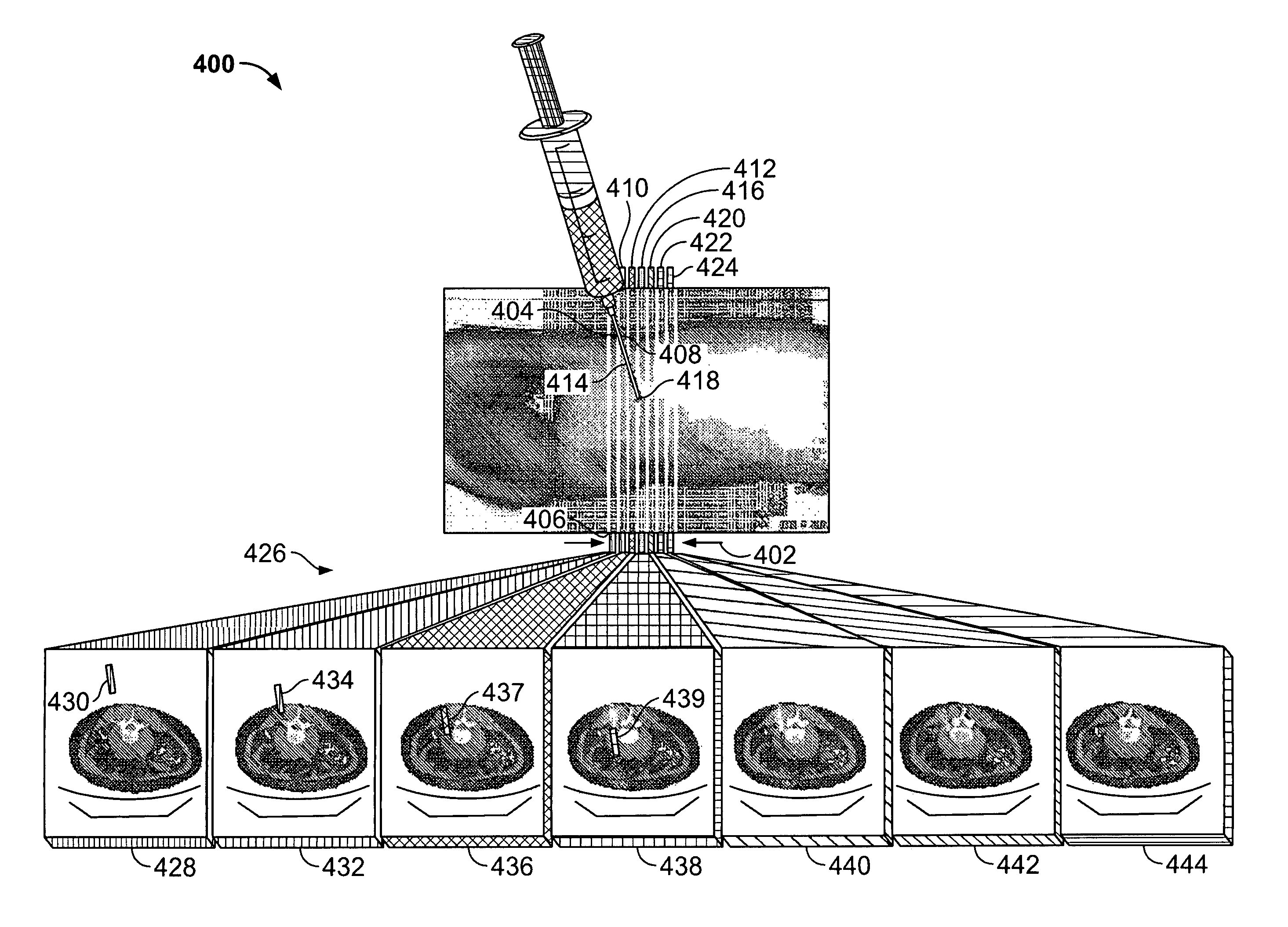
"The patent describes an imaging system that can display an instrument in a region of interest. The system uses a multi-slice detector and a processor to identify the instrument in the images and display it with an indicator associated with the slice. The system can also track the instrument relative to a target and automatically move the scan plane of the imaging system to observe the instrument's movement. The technical effects of this invention include improved accuracy and efficiency in identifying and tracking the position of an instrument in a region of interest, which can aid in the diagnosis and treatment of various medical conditions."

Problems solved by technology

However, increasing the frame rate generally adversely affects minimizing image degradation.
For example, an increase in the frequency that projection data is filtered, weighted and backprojected, tends to slow the frame rate.
The frame rate is thus limited to the computational capabilities of the CT Fluoro system.
As the number of acquired slices per gantry rotation offered in multi-slice CT systems increases, the user is unable to use all the information available.
More specifically, in interventional CT procedures the user is challenged when attempting to monitor multi-slice scanners which are capable of presenting multiple images at frame rates often exceeding approximately 10 frames per second.
With multi-slice CT Fluoro systems, one to three thick-slice summations of the available thinner axial slices can be presented as summed images, however, such a summation foregoes the potential resolution enhancement afforded by thin slice imaging.
As a result, such summation may not provide the possible improved needle placement accuracy afforded by multi-slice scanners.
Additionally, the trajectory of the needle insertion during the interventional procedure (biopsy, drainage etc.) may be different from the axial plane such that in conventional CT single-slice interventional procedures, the needle insertion is generally limited to the image plane only and any Z direction needle position change requires patient table movement in the appropriate direction.
Moreover, there is an added risk of moving the patient table and patient In and Out of the gantry aperture during the procedure while the needle remains inserted in the patient's body.

Method used


Image

  • Methods and systems for tracking instruments in fluoroscopy
  • Methods and systems for tracking instruments in fluoroscopy
  • Methods and systems for tracking instruments in fluoroscopy

Examples


Embodiment Construction

[0023] As used herein, an element or step recited in the singular and preceded with the word “a” or “an” should be understood as not excluding plural said elements or steps, unless such exclusion is explicitly recited. Furthermore, references to “one embodiment” of the present invention are not intended to be interpreted as excluding the existence of additional embodiments that also incorporate the recited features.

[0024] Also as used herein, the phrase, “reconstructing an image” is not intended to exclude embodiments of the present invention in which data representing an image is generated but a viewable image is not. Therefore, as used herein the term, “Image,” broadly refers to both viewable images and data representing a viewable image. However, many embodiments generate (or are configured to generate) at least one viewable image. Additionally, although described in detail in a CT medical setting, it is contemplated that the benefits accrue to all imaging modalities including, ...


PUM


Abstract

Methods and systems for displaying an instrument in a region of interest are provided. The imaging system includes a multi-slice detector, a processor coupled to the multi-slice detector, and a display configured to display reconstructed images. The processor is configured to receive a plurality of multi-slice scan data, identify at least a portion of an instrument in at least one slice of the plurality of multi-slice scan data, and display the identified instrument portion with an indicator associated with the at least one slice.

Description

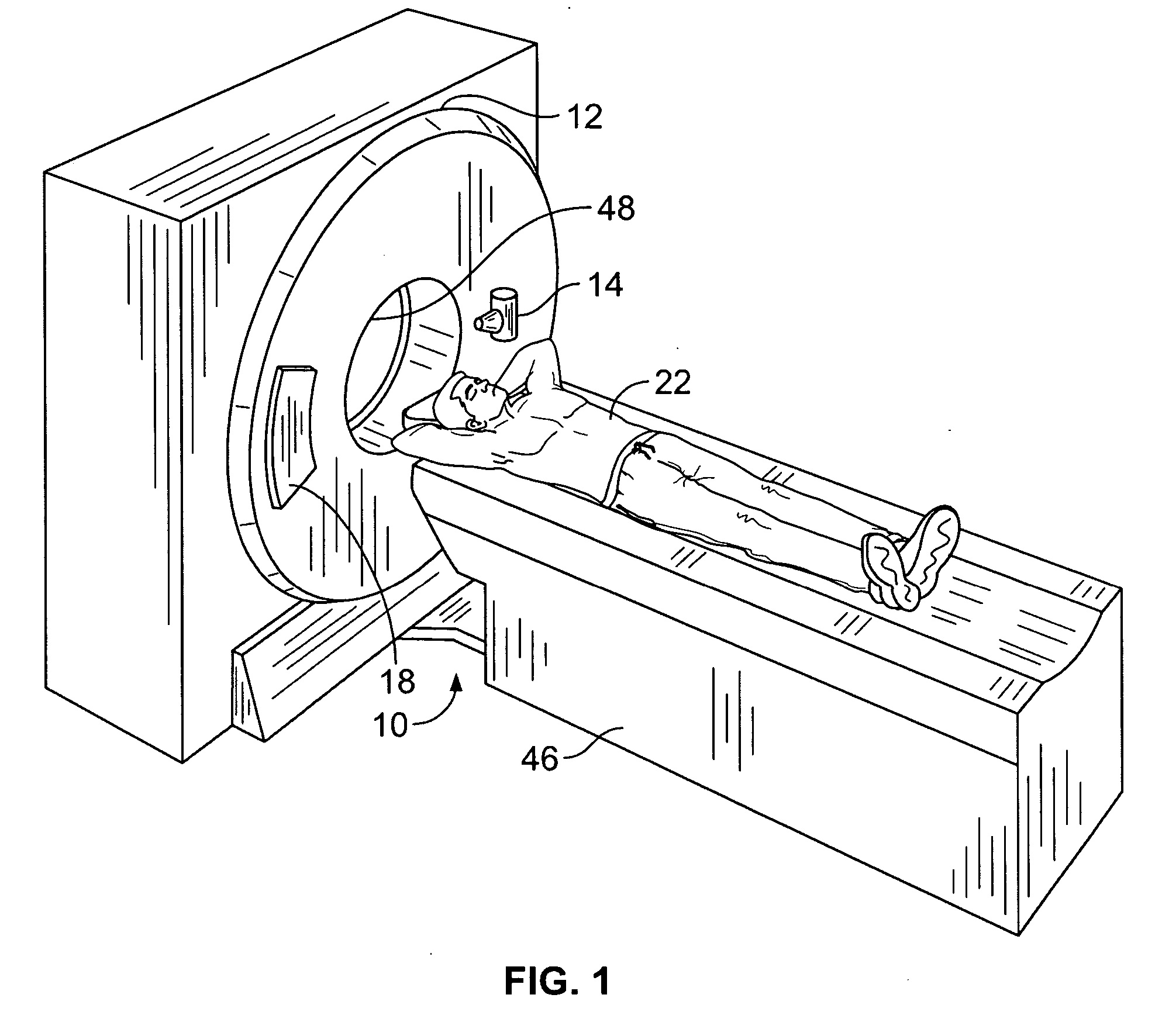
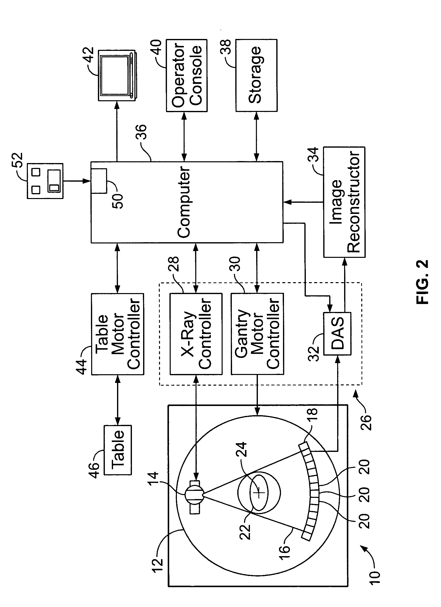
BACKGROUND OF THE INVENTION [0001] This invention relates generally to computed tomography (CT) imaging and more particularly, to tracking instruments during interventional CT Fluoroscopy. [0002] In at least one known CT system configuration, an x-ray source projects a fan-shaped beam which is collimated to lie within an X-Y plane of a Cartesian coordinate system and generally referred to as the “imaging plane” The x-ray beam passes through the object being imaged, such as a patient. The beam, after being attenuated by the object, impinges upon an array of radiation detectors. The intensity of the attenuated beam radiation received at the detector array is dependent upon the attenuation of the x-ray beam by the object. Each detector element of the array produces a separate electrical signal that is a measurement of the beam attenuation at the detector location. The attenuation measurements from all the detectors are acquired separately to produce a transmission profile. [0003] In kn...

Claims


Application Information

Patent Timeline
Patent Type & Authority Applications(United States)
IPC IPC(8): A61B5/05
CPCA61B6/032A61B6/4085A61B6/463
Inventor ARENSON, JEROME STEPHENRUIMI, DAVIDMEIRAV, ODEDGELMAN, HAIM E.
Owner GENERAL ELECTRIC CO
Learn More