
Clamping device for a tool

a technology of a tool and a clamping device, which is applied in the direction of turning machine accessories, metal-working apparatus, chucks, etc., can solve the problems of rear end in a state of suspension without, the structure of the machine has to be changed, and the manufacturers' puzzle, so as to promote machining precision and improve the steady machining condition

Inactive Publication Date: 2007-05-03
PRIMETOOL MFG
View PDF7 Cites 5 Cited by
  • Summary
  • Abstract
  • Description
  • Claims
  • Application Information

AI Technical Summary

Benefits of technology

"The present invention provides a clamping device for a tool that helps support the clamping member and acts as a cushion to improve machining precision. The device includes a conical part at the end of the clamping member for clamping with the machine, a holding part at the middle section, and a retaining recess at the other end for fixing with the tool. A fitting ring passes over the conical part and is attached to the holding part for the machine to press against in case of clamping the conical part. This helps to assist the support of the clamping member and provides a function of cushion."

Problems solved by technology

However, the preceding arrangement has a problem that the rear end is in a state of suspending without contacting with the tool handle due to only the taper part of the tool being clamped.
But, another problem is created that structure of the machine has to be changed and it is a puzzle to the manufacturers because the original machine has to be sent back to the shop for revising the structure thereof or replacing new parts.
Further, in casing of the revised structure, especially the press part, being redesigned improperly, another big problem has to be faced undesirably.

Method used


Image

  • Clamping device for a tool
  • Clamping device for a tool
  • Clamping device for a tool

Examples


Embodiment Construction

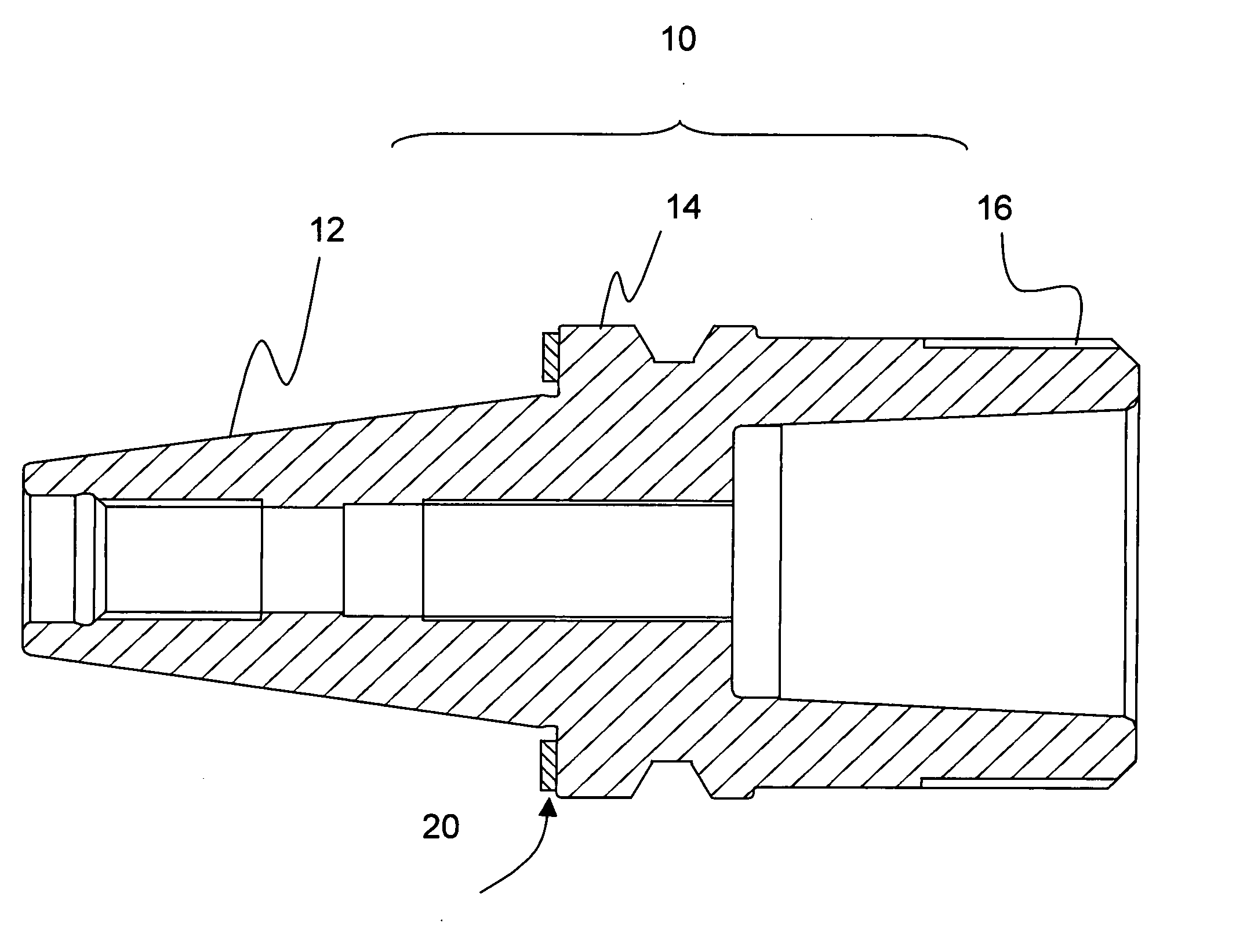
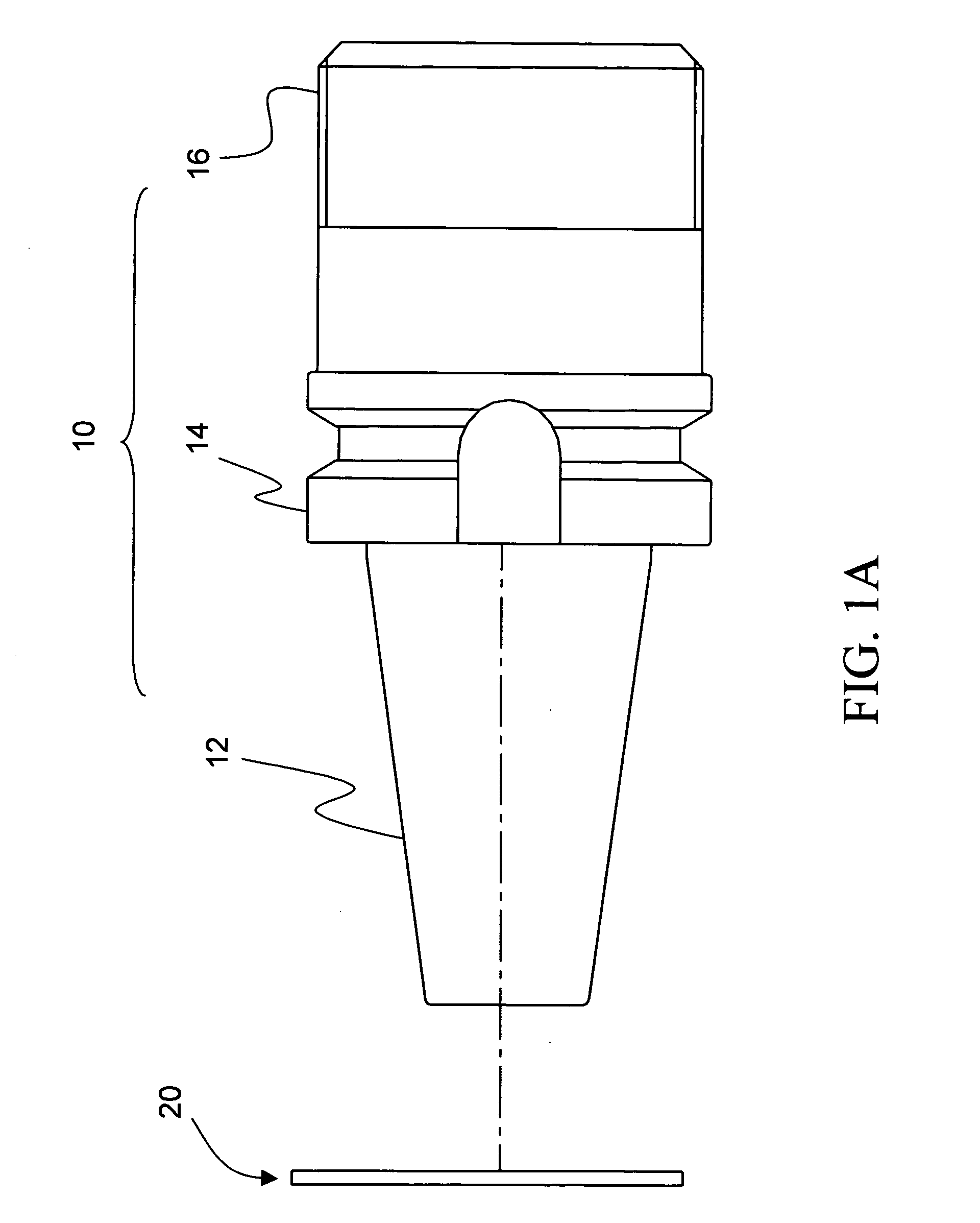
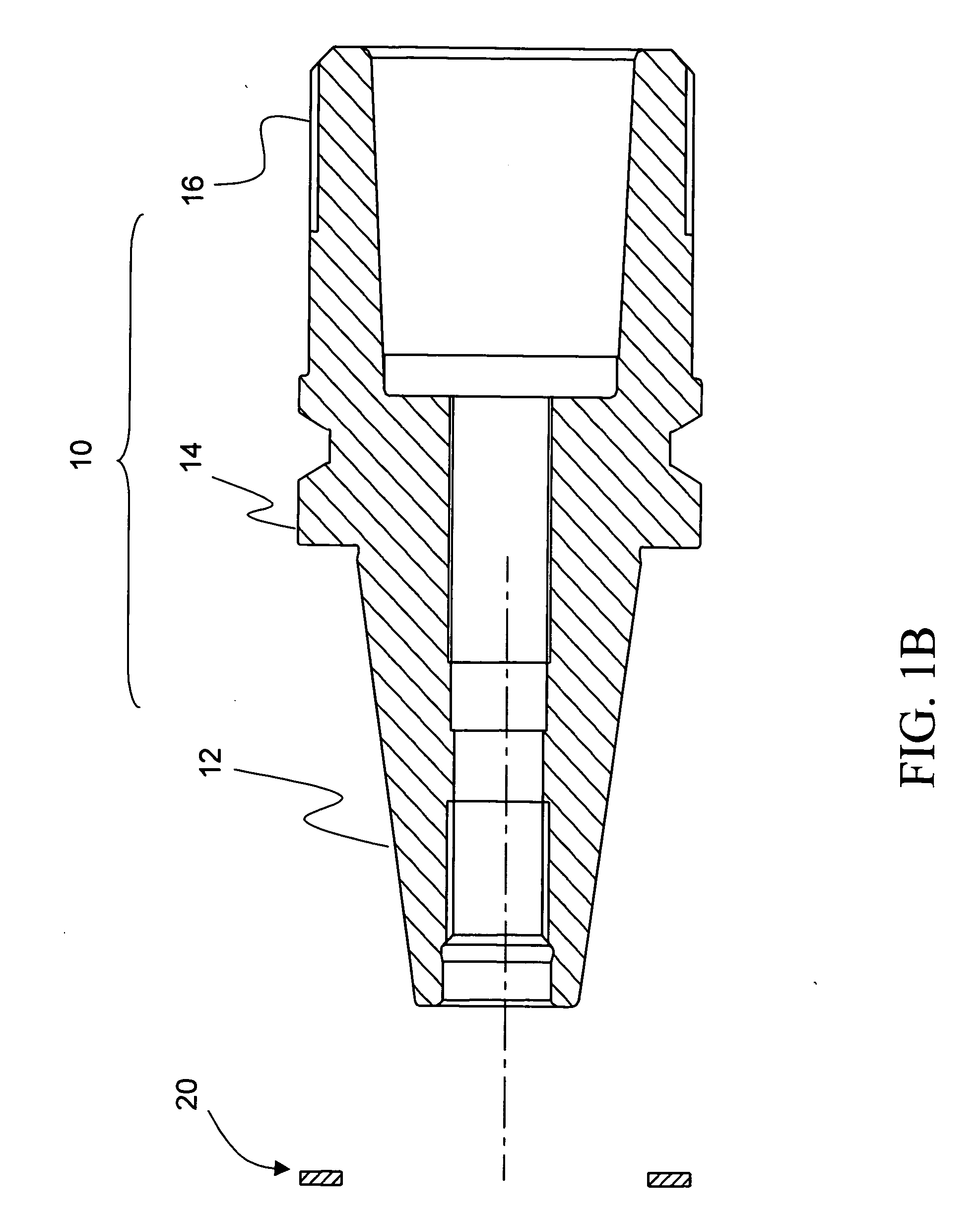
[0014] Referring to FIGS. 1A and 1B, a clamping device for a tool according to the present invention includes a clamping member 10 and a fitting ring 20. The clamping member 10 has a conical part 12 at the front section thereof, a holding section 14, which extends outward circumferentially, at the middle section thereof, and a retaining recess 16 at the rear section thereof. The retaining recess 16 is capable of connecting with a tool such as a milling cutter or a drill on the CNC machine and the conical part 12 is joined to the machine. The fitting ring 20 basically is a circular ring with an inner diameter slightly greater than the diameter of the outer end of the conical part 12 and slightly less than the outer diameter of the holding part 14 such that the fitting ring 20 is able to be attached to the holding part 14 directly via passing over the outer end of the conical part 12 without falling down.

[0015] Referring to FIGS. 2A and 2B, the fitting ring 20 is attached to the late...


PUM

PropertyMeasurementUnit
thicknessaaaaaaaaaa
lengthaaaaaaaaaa
structureaaaaaaaaaa

Abstract

A clamping device for a tool being joined to a machine includes a clamping member and a fitting ring. Thickness of the fitting ring being greater than a length between the conical part and the holding part of the clamping member allows the machine pressing against the fitting ring in case of the machine clamping the conical part with more steady clamping and achieving an effect of cushion.

Description

FIELD OF THE INVENTION [0001] The present invention relates to a clamping device for a tool being mounted to a machine and particularly to a clamping device, which provides a fitting ring for cushioning and assisting the tool being clamped. BACKGROUND OF THE INVENTION [0002] Generally, the CNC (computerized numerical control) machine has been indispensable for work pieces being machined with operations such as drilling, reaming, boring and milling. Cutting tools are usually mounted to the machine with the tool handle or tool stem thereof being joined to the spindle of the machine respectively. The tool handle has a taper part at the front end thereof for being clamped by the machine and the rear end thereof is for being attached to the cutter such that the cutting tools are able to be held to the machine. [0003] The taper part provides an advantage that precise dimension of the respective tool handle for accommodating different machines is not required and the taper part slants grad...

Claims


Application Information

Patent Timeline
Patent Type & Authority Applications(United States)
IPC IPC(8): B23C5/00
CPCB23B31/006B23B2222/04B23B2240/21Y10T279/17965B23B2260/114Y10T409/30952Y10T408/95B23B2250/16
Inventor CHEN, PETER
Owner PRIMETOOL MFG
Learn More