Band saw machine, saw blade installation method in band saw machine, saw blade driving method, and cutting method
a band saw machine and installation method technology, which is applied in the direction of band saws, metal sawing accessories, manufacturing tools, etc., can solve the problems of easy vibration, difficult miniaturization, and large vertical dimension of the whole horizontal band saw machine, and achieve the effect of reducing the reaction for
- Summary
- Abstract
- Description
- Claims
- Application Information
AI Technical Summary
Benefits of technology
Problems solved by technology
Method used
Image

Examples
first embodiment
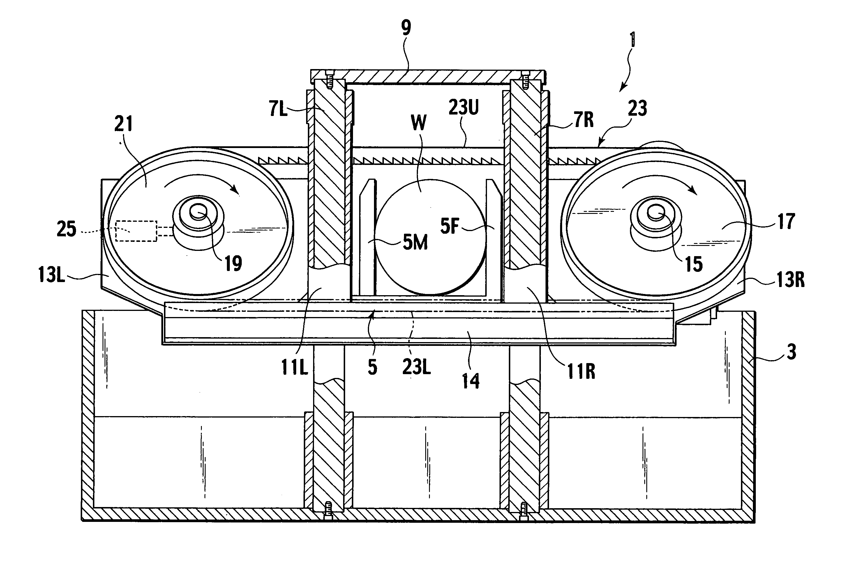
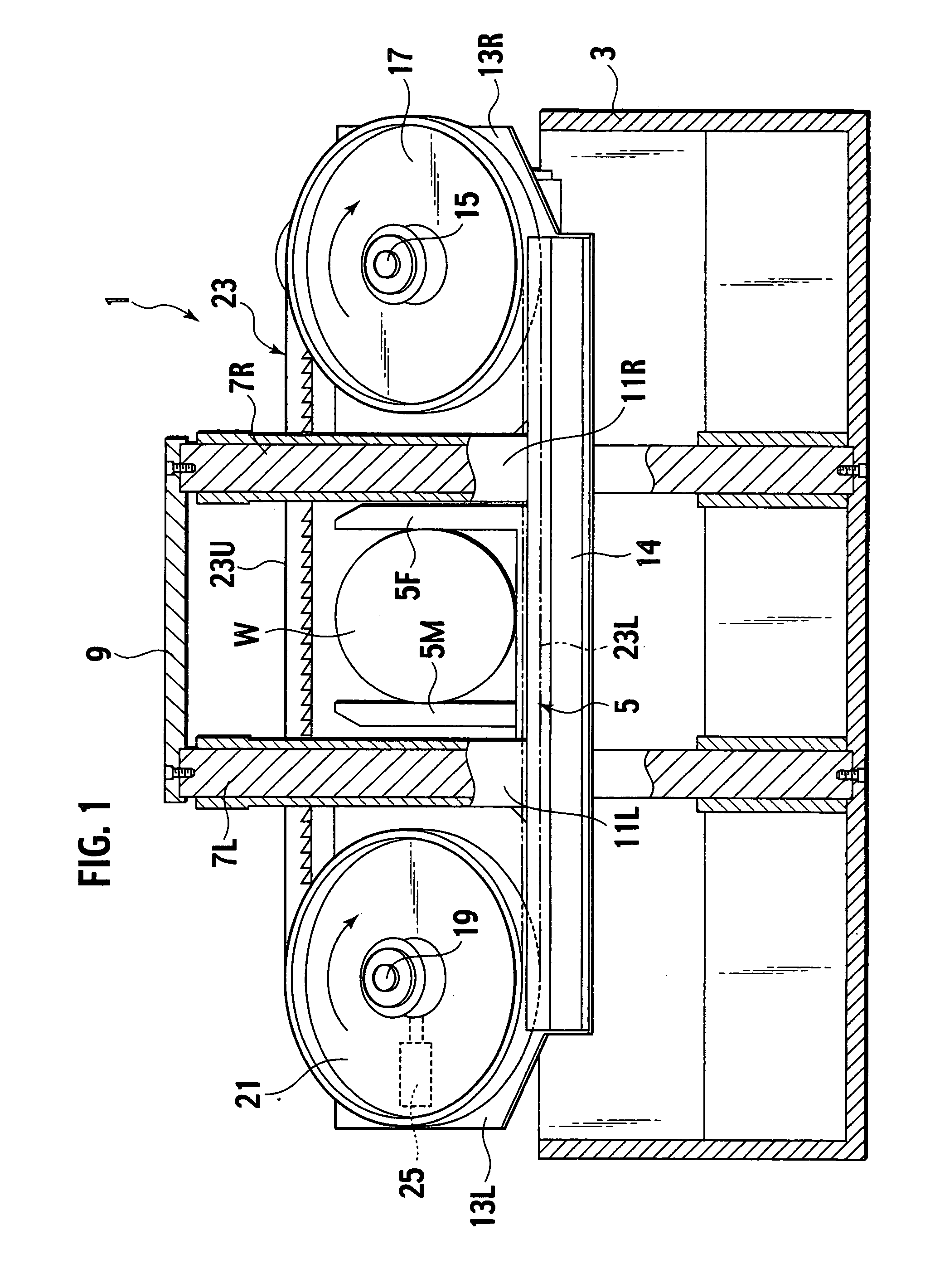
[0085]FIG. 1 shows a band saw machine in accordance with the present invention, in particular, a horizontal band saw machine 1. The horizontal band saw machine 1 is provided with a box-like base frame 3 and a vise device 5 having a fixed vise jaw 5F and a movable vise jaw 5M on the upper face of the base frame 3, which can fixedly hold a work W therebetween and are located opposite to each other. Since the configuration of the vise device 5 is general and publicly known, detailed description of the vise device 5 is omitted.
[0086] Hereinafter, when describing the horizontal band saw machine 1, a direction in which a material is sent is defined as an X-axis direction, a direction perpendicular to the X-axis direction in which the saw blade runs is defined as a Y-axis direction, a direction in which the material advances to be cut in the X-axis direction is defined as a forward direction (represented by “F” in FIG. 21 and FIG. 27) and a direction in which the cut material retreats is d...
second embodiment
[0103] Next, the present invention will be described with reference to figures.
[0104]FIG. 3 to FIG. 7 show a double-post horizontal band saw machine 1 having a band saw blade attachment auxiliary device according to the present invention. The horizontal band saw machine 1 is provided with the box-like base frame 3, a cut material carrying table 4 for carrying a cut material W to the horizontal band saw machine 1 which is disposed on the upper face of the base frame 3 and in the rear side of the horizontal band saw machine 1 (back face side of the sheet of FIG. 3, left side in FIG. 5) and a product receiving table 6 for supporting the product W cut in the horizontal band saw machine 1 which is disposed on the upper face of the base frame 3 and in the front side of the horizontal band saw machine 1 (front face side of the sheet of FIG. 3, right side in FIG. 5).
[0105] The cut material carrying table 4 is provided with the vise device 5 (5F, 5M) having the fixed vise jaw 5F and the mov...
third embodiment
[0134] Next, the present invention will be described with reference to figures.
[0135] Referring to FIG. 12 to FIG. 14, a horizontal band saw machine 201 as a saw machine in accordance with the third embodiment has a base 203 and left and right guide posts 205 are vertically installed on the base 203 in FIG. 12. A saw blade housing 207 that has a band saw blade B as a cutting tool therein is guided to the guide posts 205 so as to vertically slide using guiding members 209. The vertical movement of the saw blade housing 207 is performed by operating a lifting hydraulic cylinder 211 as a saw blade cutting driving device provided on the base 203. The lifting hydraulic cylinder 211 can control cutting of the work W as a cut material with the band saw blade B and separation of the band saw blade B from the work W.
[0136] In FIG. 12, a saw blade position detecting encoder 213 is provided at the left guiding member 209 and the moving speed of the saw blade housing 207, that is, the cutting ...
PUM
| Property | Measurement | Unit |
|---|---|---|
| Angle | aaaaa | aaaaa |
| Volume | aaaaa | aaaaa |
| Volume | aaaaa | aaaaa |
Abstract
Description
Claims
Application Information
 - R&D
- Intellectual Property
- Life Sciences
- Materials
- Tech Scout
- Unparalleled Data Quality
- Higher Quality Content
- 60% Fewer Hallucinations
Browse by: Latest US Patents, China's latest patents, Technical Efficacy Thesaurus, Application Domain, Technology Topic, Popular Technical Reports.
© 2025 PatSnap. All rights reserved.Legal|Privacy policy|Modern Slavery Act Transparency Statement|Sitemap|About US| Contact US: help@patsnap.com