
Use of a silicon carbide-based ceramic material in aggressive environments

a ceramic material and silicon carbide technology, applied in the field of ceramic materials for use in aggressive environments, can solve the problems of the relatively high the inability to fully dissolve the binder, and the inability to achieve the effect of reducing the cost of the binder,

Inactive Publication Date: 2007-04-19
LOUIS PASTEUR DE STRASBOURG UNIV +2
View PDF13 Cites 1 Cited by
  • Summary
  • Abstract
  • Description
  • Claims
  • Application Information

AI Technical Summary

Benefits of technology

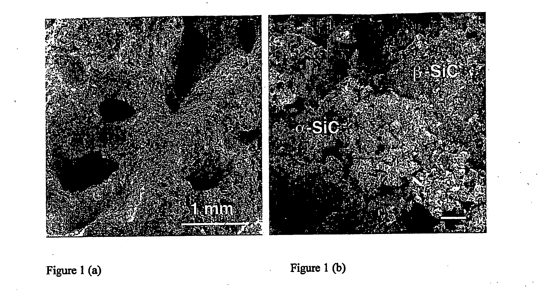
The present invention solves the problem of replacing the oxide-based binders used in known methods by using a matrix consisting of β-silicon carbide and adding inclusions. This material can be produced by preparing a precursor mixture of β-SiC precursor and a carbonated resin, shaping it into panels or bricks, and then polymerizing the resin. The resulting material has improved mechanical resistance and reduced porosity. The invention also provides a method for producing the material by heating the precursor mixture at a specific temperature and for a specific duration to form a final element with specific mechanical resistance.

Problems solved by technology

Its relatively high cost is associated with the use of high temperatures during synthesis.
In fact, it is observed that, in some applications of this material, the presence of corrosive products, such as acids or fluorinated compounds or strongly basic products, induces a progressive destruction of the compounds contained in the binder.
This eventually leads to the total dissolution of said binder, and, as a result, the destruction of the macroscopic shape of the material.
Nevertheless, the examples given only relate to compositions of the deposition layer and the observation of the latter with an electron microscope without providing more information on the increased resistance of said composite with respect to oxidation or aggressive environments which represent the intended end purpose.
A specific drawback of this method is the possible appearance of microcracking between the protective layer and the composite during the production or use of elements coated in this way, due to differences between the heat expansion coefficients.
However, SiO escapes very rapidly from the reaction environment before the reaction (3) is complete and, for this reason, induces a non-negligible loss of the initial silicon, leaving a large quantity of non-reacted carbon in the final material.
However, the SiC formed using this method is always in the form of very fine powder and requires another pre-forming step with binders before use.
These binders are liable to be corroded by strongly acidic or basic solutions resulting in the destruction of the macroscopic structure of the material.

Method used


Image

  • Use of a silicon carbide-based ceramic material in aggressive environments
  • Use of a silicon carbide-based ceramic material in aggressive environments

Examples


example 1

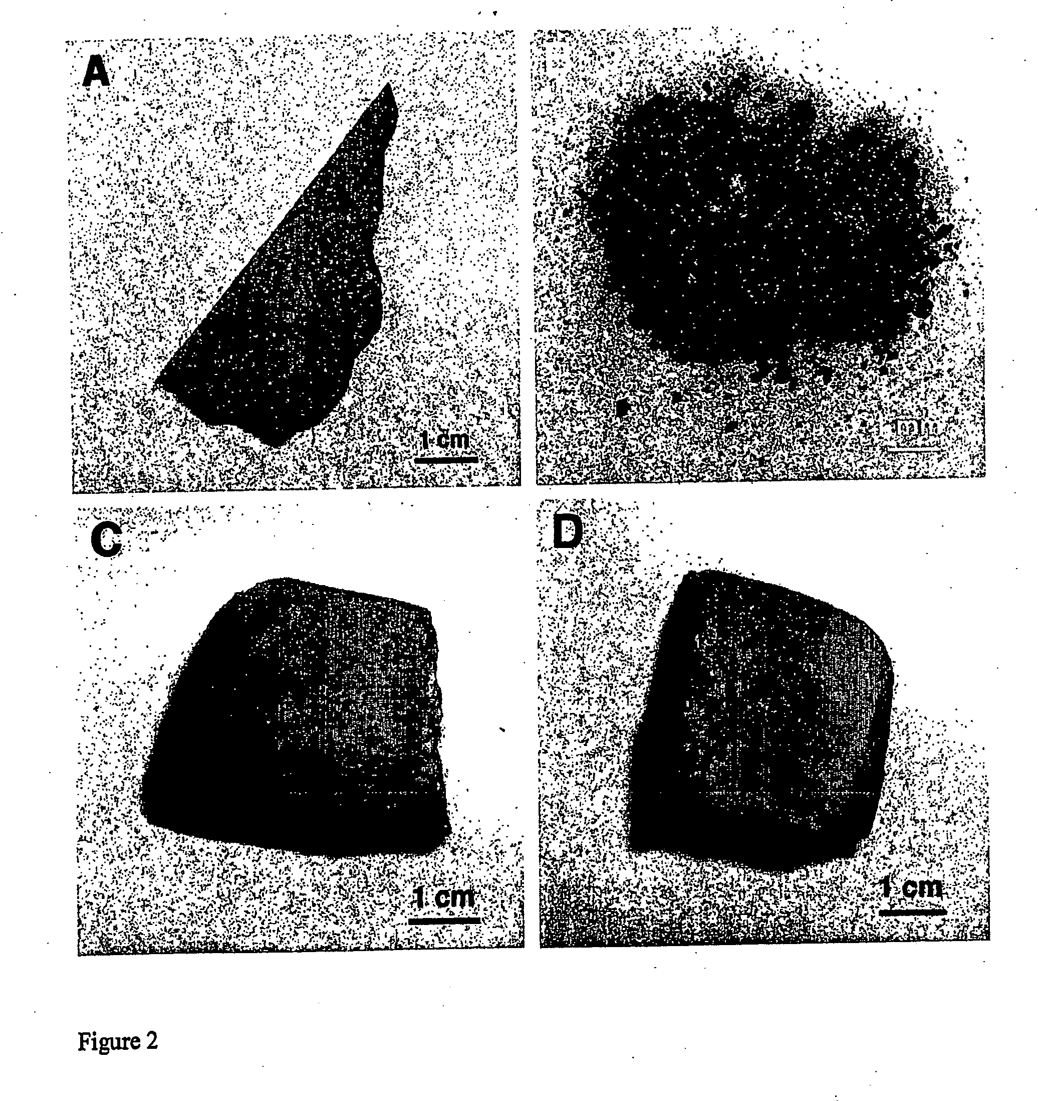
Production of β-SiC Panels Without Inclusions

[0063] 1500 g of silicon powder (grain size focused on 7 μm), 560 g of carbon black (grain size focused on 20 nm) and 1000 g of phenolic resin are mixed in a mixer.

[0064] The paste obtained in this way is then compressed between two flat surfaces to obtain a 3 mm thick panel. This panel is hardened by heating at 200° C. for 3 hours. During this step, a weight loss corresponding to approximately 10% of the initial weight of the mixture is observed. The element obtained is easy to handle and has a smooth surface appearance.

[0065] Said element is then subject to progressive heating under a flow of argon at atmospheric pressure up to 1360° C., and it is then kept at this temperature for one hour. The element is then allowed to cool to ambient temperature. During this step, a weight loss corresponding to approximately 13.5% of the hardened element is observed. The appearance of the material is black as it still contains 7% free carbon.

[006...

example 2

Production of β-SiC Panels with α-SiC Inclusion (α-SiC / β-SiC Composite)

Alternative Embodiment (a)

[0068] 4.5 g of silicon powder (average particle diameter: approximately 7 μm) is mixed with 5.5 g of a phenolic resin providing the source of carbon required for the carburisation to form the β-SiC intended to act as a binder in the final composite. 7 g of α-SiC in powder form is added to this mixture as a source of inclusions. The mixture was shaped by means of moulding.

[0069] The whole is polymerised in air at 150° C. for 2 hrs. The weight loss during this polymerisation was 2 grams. The solid obtained in this way is subjected to a heat treatment in a dynamic vacuum at 1300° C. with a temperature rise slope of 5° C. min−1. During the temperature rise, the polymerised resin is carbonised and results, at high temperatures, in a carbon network in close contact with the silicon grains, facilitating SiC synthesis. The composite is kept at this temperature for 2 hrs so as to convert the ...

embodiment (

Alternative Embodiment (b)

[0073] In other alternative embodiment, a mixture of 4.5 g of silicon powder, 5.5 g of phenolic resin and 73 g of α-SiC grains is produced. The mixture is shaped by means of pressing such that the resin and the silicon powder fill most of the free volume between the α-SiC grains.

[0074] The same procedure as for example 2(a) is then followed.

[0075] The product obtained then consists of a mixture of 91% α-SiC bound with 9% β-SiC and has a density of 2.5 g / cm3 with an open porosity of less than 20%.


PUM

PropertyMeasurementUnit
densityaaaaaaaaaa
densityaaaaaaaaaa
temperaturesaaaaaaaaaa

Abstract

A SiC-based composite material capable of use as an inner coating for an aluminium smelting furnace or as an inner coating for a fused salt electrolytic cell, wherein said composite material has been prepared from a precursor mixture comprising at least one β-SiC precursor and at least one carbonated resin, and wherein said composite material contains inclusions, and wherein at least one part thereof comprises α-SiC, in a β-SiC matrix.

Description

FIELD OF THE INVENTION [0001] The present invention relates to ceramic materials for use in aggressive environments, as found particularly in chemical and electro-metallurgical engineering, and more specifically the refractory bricks used in smelting furnaces or electrolytic cells. STATE OF THE RELATED ART [0002] Liquid metals and fused salts are among the most aggressive chemical agents known. As numerous metallurgical and electro-metallurgical industrial processes involve the melting of metals and / or salts, there is a need for refractory materials which can withstand such an environment. Equipment for molten metals or fused salts, typically smelting furnaces or fused salt electrolytic cells, require an inner coating consisting of large quantities of refractory bricks or panels and the replacement of said refractory elements, also referred to as relining, immobilises the equipment for some time. Therefore, a material with an improved service life in such an environment may result i...

Claims


Application Information

Patent Timeline
Patent Type & Authority Applications(United States)
IPC IPC(8): C01B31/36C04B35/573C04B35/577C04B35/622C04B35/634C04B35/64C25C3/08
CPCB82Y30/00C04B35/565C04B35/573C04B2235/3217C04B2235/3418C04B2235/383C04B2235/3834C04B2235/3873C04B2235/3886C04B2235/424C04B2235/428C04B2235/48C04B2235/5244C04B2235/526C04B2235/5436C04B2235/5454C04B2235/762C04B2235/767C04B2235/77C04B2235/80C04B2235/85C04B2235/9684C04B2235/9692C25C3/085
Inventor PHAM, CHARLOTTEPHAM-HUU, CUONGLEDOUX, MARC-JACQUESNGUYEN, PATRICKS
Owner LOUIS PASTEUR DE STRASBOURG UNIV
Learn More