Electrically conductive paste and multilayer ceramic substrate

Active Publication Date: 2007-04-12
MURATA MFG CO LTD
View PDF16 Cites 12 Cited by
  • Summary
  • Abstract
  • Description
  • Claims
  • Application Information

AI Technical Summary

Benefits of technology

[0039] Preferably, the content of the inorganic component disposed on the surfaces of the metal powder in the electrically conductive paste according to an aspect of the present invention is 0.5 to 8 percent by weight relative to the total weight of the metal powder and the inorganic component, as described above, and 1 to 7 percent by weight is more preferable. The above-described content of the inorganic component also depends on the state of adhesion of the inorganic component to the surfaces of the metal powder or the surface area of the metal powder. The metal powder having a small average particle diameter, for example, an average particle diameter of 0.5 μm or less, has a relatively large specific surface area and, therefore, the sintering suppression effect becomes inadequate when the content of the inorganic component is less than 0.5 percent by weight. On the other hand, the metal powder having a large average particle diameter, for example, an average particle diameter of 10 μm or more, has a relatively small specific surface area and, therefore, when the content of the inorganic component exceeds 8 percent by weight, the thickness of the film consisting of the inorganic component becomes excessive and the sintering start effect of the glass frit is not exerted. The excessive presence of the inorganic component may lead to reduction in the electrical conductivity and, therefore, it is not preferable.

Problems solved by technology

However, in general, since the electrically conductive paste for forming the wiring conductor starts shrinking in a temperature range lower than the sintering temperature capable of sintering the ceramic layer, a difference in shrinkage behavior occurs between the ceramic layer and the wiring conductor.
Consequently, a stress resulting from this difference in shrinkage behavior may cause an occurrence of structural defect, e.g., crack or delamination, in a produced multilayer ceramic substrate.
However, the electrically conductive paste in each of the above-described Patent Documents 1 to 3 has the following problems to be overcome.
Such a sintering inhibitor cannot completely suppress the solid phase mutual sintering of electrically conductive component.
Furthermore, since the sintering of the electrically conductive paste depends on glass diffusing from the glass ceramic substrate, unsintered regions may be left in the conductor in the case where the size of the conductor to be formed from the electrically conductive paste is large as compared with the diffusion distance of the glass or in the case where the amount of glass component diffusing from the glass ceramic substrate is not adequate.
However, the electrically conductive paste described in Patent Document 2 cannot completely suppress the mutual sintering of the electrically conductive component as in the case of the electrically conductive paste described in Patent Document 1.
However, as in the case of the electrically conductive paste in the above-described Patent Documents 1 and 2, this cannot completely suppress the sintering of copper.
Furthermore, in the case where the softening point of the glass component constituting the glass powder is at least 300° C. lower than the firing temperature applied to the firing step for producing the ceramic substrate, the sintering behavior of the electrically conductive paste is not varied and, in addition, sintering of the ceramic substrate occurs at a temperature lower than a predetermined sintering temperature by diffusion of softened glass into an unsintered ceramic substrate and a plurality of regions having mutually different sintering temperatures are formed in the ceramic substrate, so that this may cause an occurrence of cracking and the like.
Since the surface of the copper powder exhibits inherently poor wettability with general glass, the softened glass is pushed out to the grain boundary portion during the mutual sintering of the copper powder.
As a result, large amounts of glass component may seep to the surface of the conductor.
The thus seeping glass component exerts an adverse effect when a surface treatment, such as plating, is conducted, for example.
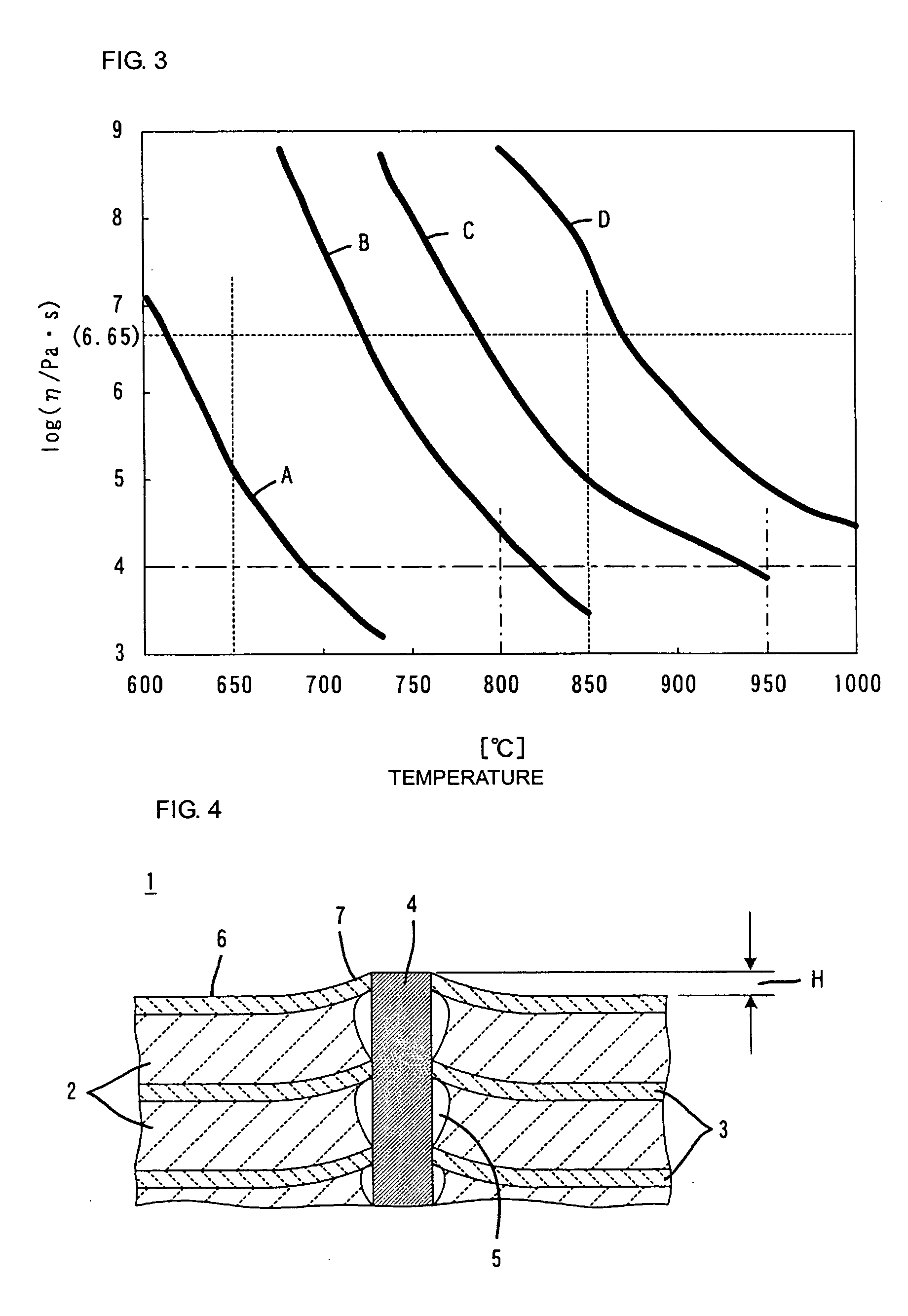
As a result, inconveniences shown in FIG. 4 may occur.
This also causes the occurrence of the above-described gap 5 and, in addition, this causes the occurrence of structural defect, e.g., crack or delamination, in the multilayer ceramic substrate 1.

Method used


Image

  • Electrically conductive paste and multilayer ceramic substrate
  • Electrically conductive paste and multilayer ceramic substrate
  • Electrically conductive paste and multilayer ceramic substrate

Examples


example 1

[0090] An electrically conductive paste composed of 82.0 percent by weight of alumina-coated copper powder, 4.5 percent by weight of glass frit composed of the glass B, and 13.5 percent by weight of organic vehicle was produced.

example 2

[0091] An electrically conductive paste composed of 82.0 percent by weight of alumina-coated copper powder, 4.5 percent by weight of glass frit composed of the glass C, and 13.5 percent by weight of organic vehicle was produced.

example 3

[0092] An electrically conductive paste composed of 76.0 percent by weight of alumina-coated copper powder, 4.0 percent by weight of glass frit composed of the glass C, 3.0 percent by weight of polypropylene powder, and 17.0 percent by weight of organic vehicle was produced.


PUM

PropertyMeasurementUnit
Temperatureaaaaaaaaaa
Percent by massaaaaaaaaaa

Abstract

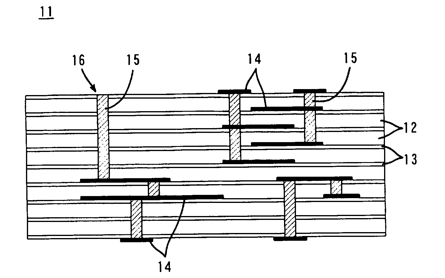
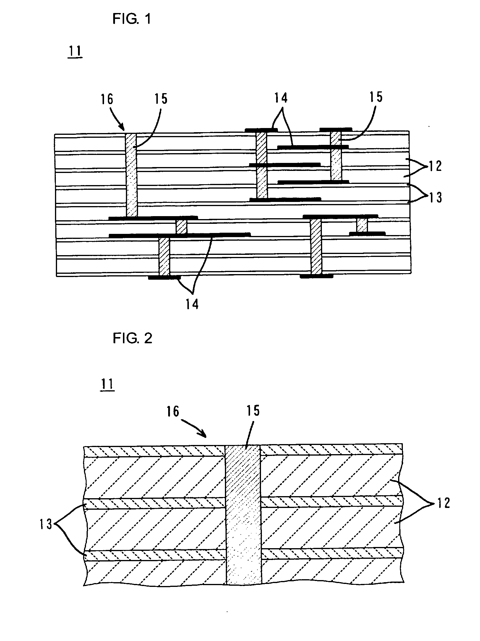
An electrically conductive paste used for forming wiring conductors, such as via holes (15) disposed on a multilayer ceramic substrate (11), is provided, wherein the temperature range, in which sintering is effected in a firing step, can be controlled relatively optimally. The electrically conductive paste contains a metal powder, a grass frit, and an organic vehicle. An inorganic component, which is not sintered at a sintering temperature capable of sintering the ceramic layers (12) included in the multilayer ceramic substrate (11) in the firing step, is disposed on particle surfaces of the metal powder. The glass frit has a softening point 150° C. to 300° C. lower than the above-described sintering temperature.

Description

TECHNICAL FIELD [0001] The present invention relates to an electrically conductive paste used for forming wiring conductors disposed in a multilayer ceramic substrate, as well as the multilayer ceramic substrate. In particular, it relates to an electrically conductive paste to be co-fired in a firing step for sintering ceramic layers in the manufacture of a multilayer ceramic substrate, as well as the multilayer ceramic substrate provided with the wiring conductors formed by using the electrically conductive paste. BACKGROUND ART [0002] An electrically conductive paste contains at least a metal powder and an organic vehicle. The electrically conductive paste has been widely used in the field of electronic components, since a conductor with a desired pattern or in a desired form can easily be formed by applying printing or the like to the electrically conductive paste. More specifically, the electrically conductive paste has been widely used for forming wiring conductors, such as con...

Claims


Application Information

Patent Timeline
IPC IPC(8): H01B1/12H01B1/16H01L23/498H05K1/09H05K3/40
CPCH01B1/16H01L23/49883H01L2924/09701H05K1/092Y10T428/24917H01L2924/0002H05K3/4061H01L2924/00H05K3/46
Inventor NOMIYA, MASATOURAKAWA, JUN
Owner MURATA MFG CO LTD
Why Eureka
Try Eureka