
Disc brake

a disc brake and disc technology, applied in the direction of noise/vibration control, slack adjusters, brake elements, etc., can solve the problems of affecting the braking performance of the disc brake, the guide member is more likely to rattle during the rearward braking operation of the vehicle, and the torque-receiving surface may become recessed

Inactive Publication Date: 2007-04-12
HITACHI LTD
View PDF0 Cites 3 Cited by
  • Summary
  • Abstract
  • Description
  • Claims
  • Application Information

AI Technical Summary

Benefits of technology

[0009] Therefore, an object of the present invention is to provide a disc brake that are designed to prevent a recess from being formed due to pressure caused by a braking operation when a vehicle is moving forward and reduce rattling during a braking operation when the vehicle is moving rearward.
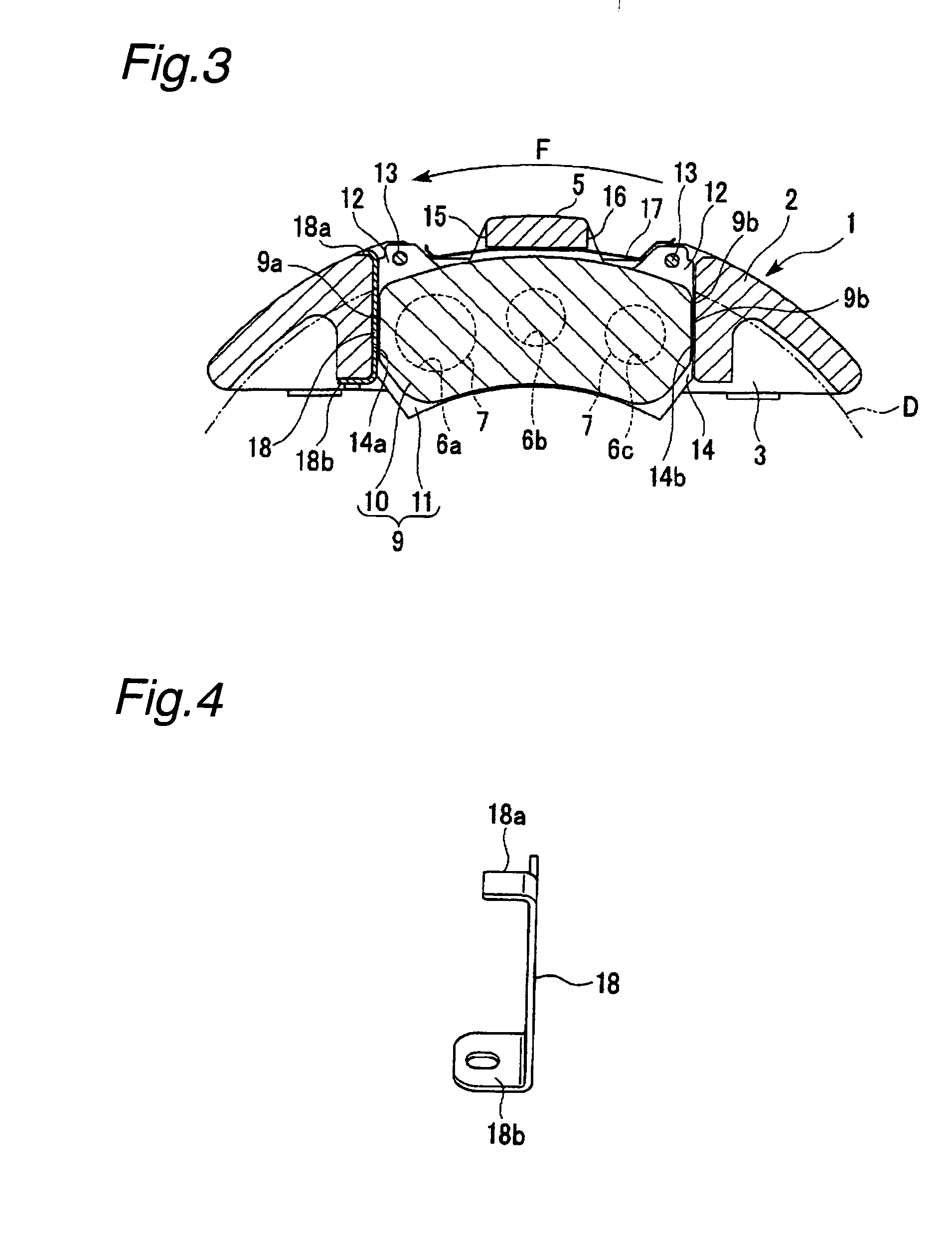
[0042] Further, the disc brake of the present embodiment requires fewer components as the rearward torque-receiving surfaces 14b are not provided with guide members. As a result, the number of parts can be decreased and a manufacturing cost can be reduced.
[0009] Therefore, an object of the present invention is to provide a disc brake that are designed to prevent a recess from being formed due to pressure caused by a braking operation when a vehicle is moving forward and reduce rattling during a braking operation when the vehicle is moving rearward.

Problems solved by technology

However, since the caliper body of this disc brake is made of a metal having a relatively low hardness such as an aluminum alloy, there is a possibility that the torque-receiving surfaces may become recessed when subject to a large torque during a braking operation.
However, it is difficult for this conventional disc brake to satisfy required braking performances for both forward and rearward movements of the vehicle, since a guide member of an equally hard material are provided on a torque-receiving surface in each direction of rotation of the disc.
Therefore, if a guide member is made of a hard material with a view to preventing formation of a pressure recess or the like caused by a braking operation of a forward moving vehicle, the guide member is more likely to rattle during a rearward braking operation of a vehicle.

Method used


Image

  • Disc brake
  • Disc brake
  • Disc brake

Examples


first embodiment

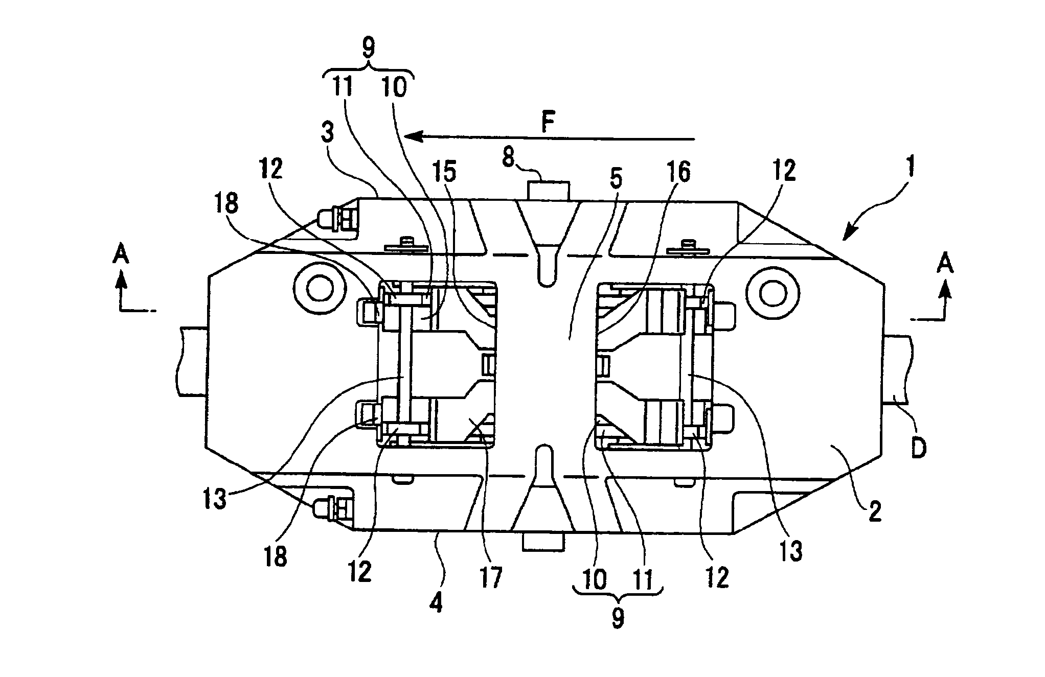
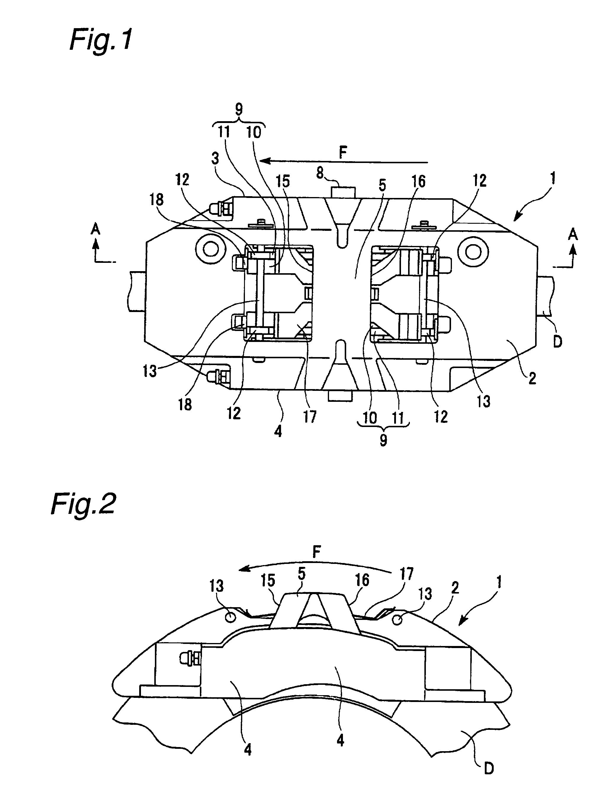
[0032] First, the disc brake according to the present invention will be described with reference to FIGS. 1 to 4.

[0033] This disc brake comprises: a brake disc (disc) D adapted to rotate with an axle; and a brake caliper 1 fixed to the side of a vehicle body. A caliper body 2 of the brake caliper 1 is made of a single block of an aluminum alloy (for example, AC1B-T4, AC2A-T6, or AC4CH-T6). It is to be noted that an arrow F in the figures indicates a direction of rotation of the brake disc D when a vehicle moves forward, and that a hardness of the aluminum alloy used in the caliper body 2 of the present embodiment is about Hv 90.

[0034] As shown in FIG. 2, the caliper body 2 is formed to be substantially arc shaped from a lateral view point, and has a guide groove (not shown) in an inner circumferential side of the arc, the guide groove being formed to cover an outer circumferential edge of the disc D. This guide groove is defined by: an inner wall 3 facing a surface of the disc D on...

second embodiment

[0049] Next, the second embodiment will be described with reference to FIGS. 8 to 10.

[0050] In the disc brake of the present embodiment, a caliper body 202 of a brake caliper 1 is made of a single block of aluminum as is the case in the first embodiment. Inner and outer walls 3 and 4 of the caliper body 202 are each provided with two pistons 7 that are arranged side by side in a rotational direction of the disc, the two pistons 7 in the inner wall 3 and the two pistons 7 in the outer wall 4 being disposed in opposing relation to each other. Brake pads 9A and 9B are provided on front surfaces of the pistons 7 on either side of the disc D. The inner and outer walls 3 and 4 each have two guide grooves 14A and 14B for slidably holding the brake pads 9A and 9B. The guide grooves 14A and 14B are provided, on opposite sides thereof in a circumferential direction, with forward torque-receiving surfaces 14Aa and 14Ba and rearward torque-receiving surfaces 14Ab and 14Bb. Opposing sides of eac...

third embodiment

[0054] Next, the third embodiment will be described with reference to FIGS. 11 and 12.

[0055] The disc brake of the present embodiment has the same numbers of pistons 7, brake pads 309, and so on as that of the first embodiment. A metal backing member 311 for each brake pad 309 has locking hooks 30 extending integrally from the metal backing member 311 in forward and rearward rotational directions of the disc. Therefore, the present embodiment is significantly different from the other embodiments in that these locking hooks 30 are hooked and locked to respective stays 31 that project from a caliper body 302. In the first embodiment, a braking torque acting in a direction of rotation on a brake pad at a time of braking is counteracted by a torque receiving surface which pushes back the brake pad, and is provided on an outgoing side of rotation of the disc D (an exit side in the direction of rotation). In contrast, in the present embodiment, a braking torque acting in a direction of ro...


PUM


Abstract

A disc brake designed to prevent formation of a pressure recess caused by a braking operation when a vehicle is moving forward, and reduce rattling caused by a braking operation when the vehicle is moving rearward. The disc brake comprises: a caliper body including pistons that are disposed in opposing relation to each other on either side of a disc; and a plurality of brake pads that are disposed in pairs on either side of the disc. The caliper body is provided with: forward torque-receiving surfaces for receiving a braking torque from the brake pads during a braking operation when the vehicle is moving forward; and rearward torque-receiving surfaces for receiving a braking torque from the brake pads during a braking operation when the vehicle is moving rearward. Only the forward torque-receiving surfaces are provided with guide members for abutment with the brake pads, while the rearward torque-receiving surfaces can be brought into direct contact with the brake pads. The caliper body is made of a material having a hardness lower than that of the guide members.

Description

BACKGROUND OF THE INVENTION [0001] 1. Technical Field [0002] The present invention relates to a disc brake for brake control of rotation of a vehicle axle. [0003] 2. Prior Art [0004] In a known vehicle disc brake, brake pads for gripping a disc are provided at opposing lateral sides of the disc and are slidably held by a caliper body made of a material such as an aluminum alloy. In this way, the disc pads can be pressed by pressing means, that is, opposed pistons into contact with the lateral sides of the disc. Further, the caliper body of the disc brake includes pad-holding portions that are provided with toque-receiving surfaces for the brake pads to receive a reaction force exerted by the disc in a direction of rotation of the disc during a braking operation. [0005] However, since the caliper body of this disc brake is made of a metal having a relatively low hardness such as an aluminum alloy, there is a possibility that the torque-receiving surfaces may become recessed when subj...

Claims


Application Information

Patent Timeline
IPC IPC(8): F16D55/00
CPCF16D65/0006F16D65/095F16D65/0971F16D65/0977F16D2055/0016F16D2055/0041F16D2055/0091F16D2200/003
Inventor SANO, TAKASHI
Owner HITACHI LTD
Learn More