
Thin cast strip with controlled manganese and low oxygen levels and method for making same

a thin cast strip and low oxygen level technology, applied in the field of casting of steel strips, can solve the problems of relatively high cost of the last two elements, achieve the effects of reducing meniscus marks, unique surface properties, and reducing mno production

Active Publication Date: 2007-04-12
NUCOR CORP
View PDF21 Cites 5 Cited by
  • Summary
  • Abstract
  • Description
  • Claims
  • Application Information

AI Technical Summary

Benefits of technology

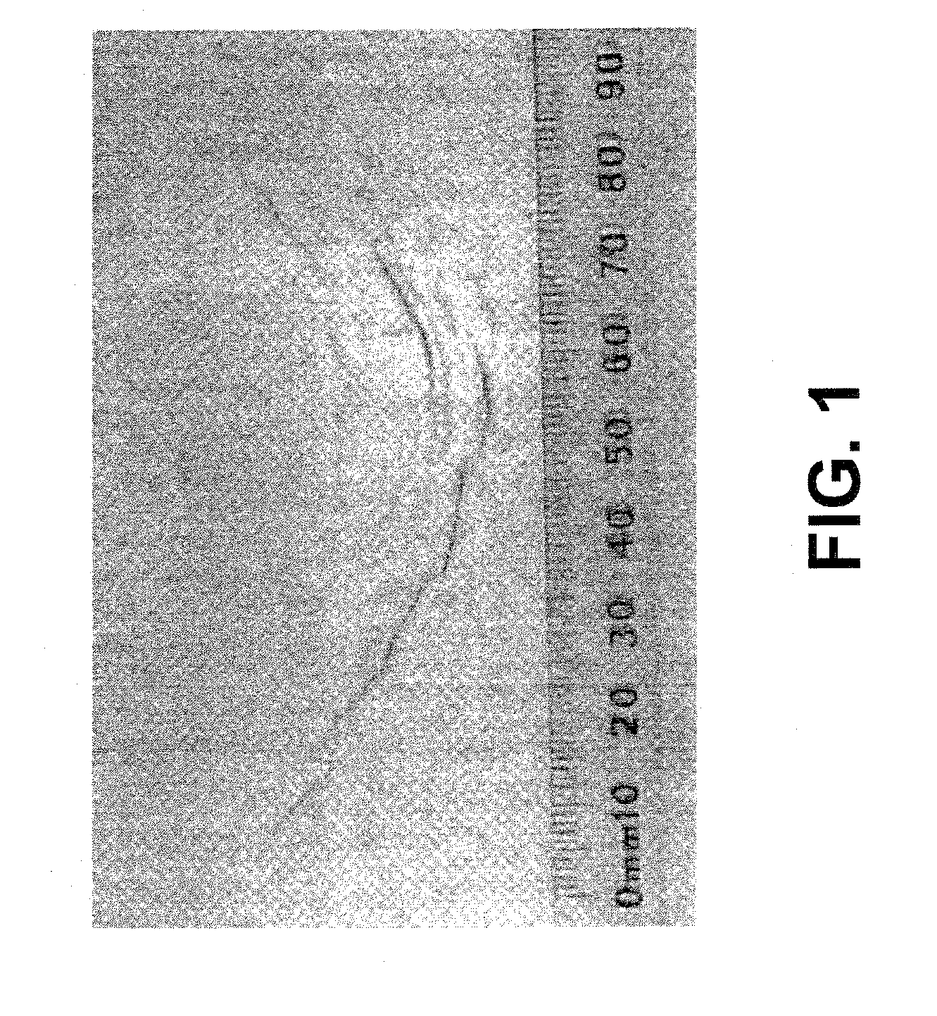
[0006] We found that by controlling the levels of manganese, silicon, calcium, aluminum and chromium in the molten steel composition, along with free oxygen levels, steel strip can be produced that has unique surface properties and production qualities with reduced meniscus marks. The oxidation of carbon to form the CO bubble is caused by the reaction of MnO in the pool slag with the carbon contained in the core nozzle. In order to substantially reduce, if not eliminate this reaction from occurring, calcium is present to react with the oxygen present and lower the amount of MnO produced. By lowering the amount of MnO produced, the oxidation reaction between the MnO and carbon in the core nozzle is substantially reduced, and meniscus marks in the resulting thin cast strip are substantially reduced.
[0032] b. means for substantially avoiding the formation of meniscus marks during strip casting, the means comprising a free oxygen content below about 50 ppm at about 1600° C. in molten steel.
[0035] b. means for substantially avoiding the formation of meniscus marks during strip casting, the means comprising a free oxygen content below about 50 ppm at about 1600° C.

Problems solved by technology

Aluminum, magnesium and titanium can form more stable oxides than manganese; however, the latter two elements are relatively expensive, and for that reason, are not of commercial use in making low carbon steel, while aluminum can be added economically.

Method used


Image

  • Thin cast strip with controlled manganese and low oxygen levels and method for making same
  • Thin cast strip with controlled manganese and low oxygen levels and method for making same
  • Thin cast strip with controlled manganese and low oxygen levels and method for making same

Examples


Embodiment Construction

[0041] For continuous strip casting, it is desirable to have a sulfur content of the order of 0.009% or lower, although other sulfur levels may be useful. Following the desulfuriziation step generally in a ladle metallurgy furnace (LMF), the deoxidized and desulfurized molten steel is reoxidized typically in the ladle in preparation for casting. As a result, the reoxidized molten steel usually contains a distribution of oxide inclusions (typically inclusions with a mixture of MnO, CaO, SiO2 and Al2O3) which influence the initial solidification of the molten metal and the formation of strip product exhibiting a characteristic distribution of solidified inclusions. Further details relating to the above-mentioned process are described in co-pending U.S. patent application Ser. No. 60 / 280,916 and U.S. patent application Ser. No. 60 / 322,261, both of which have been expressly incorporated herein by reference.

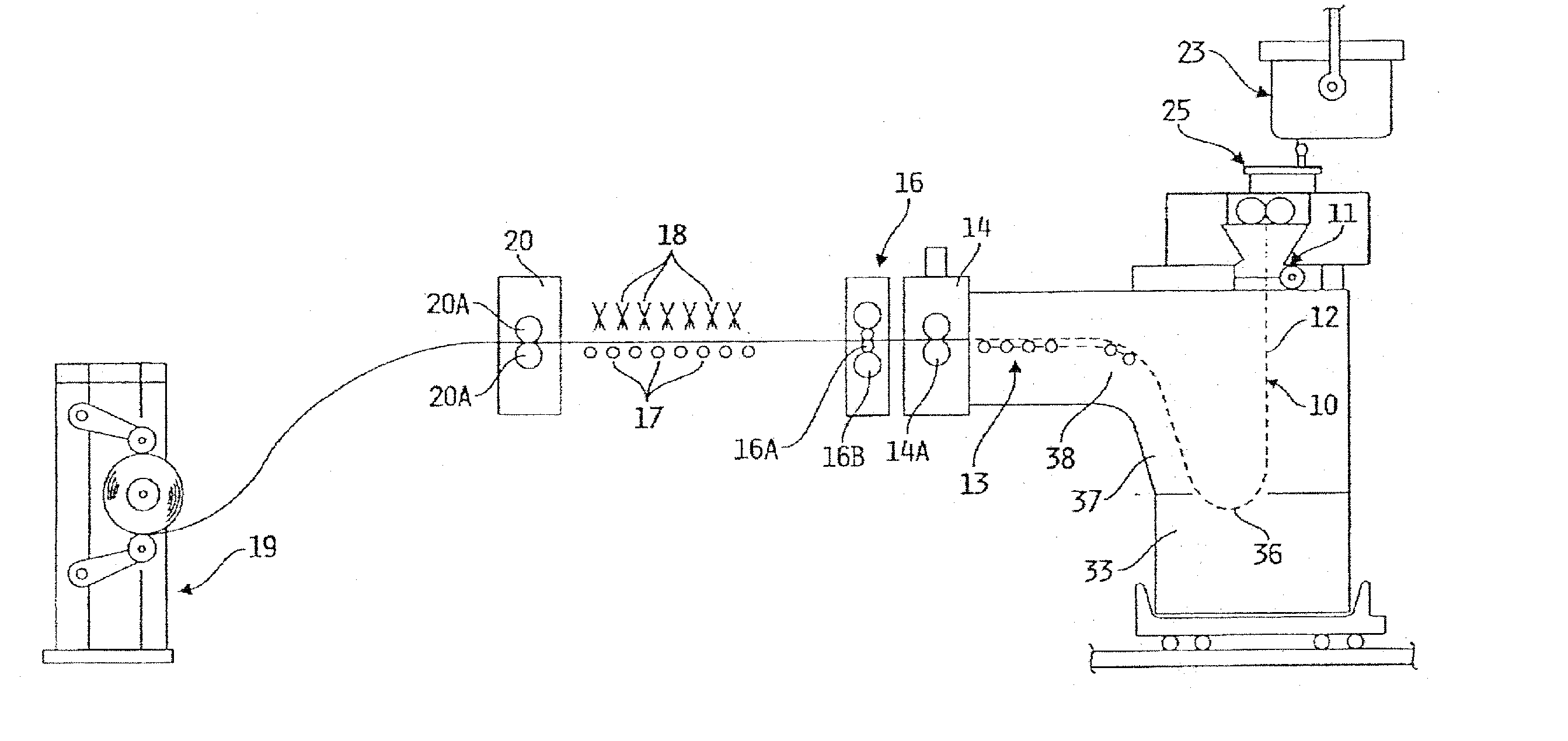
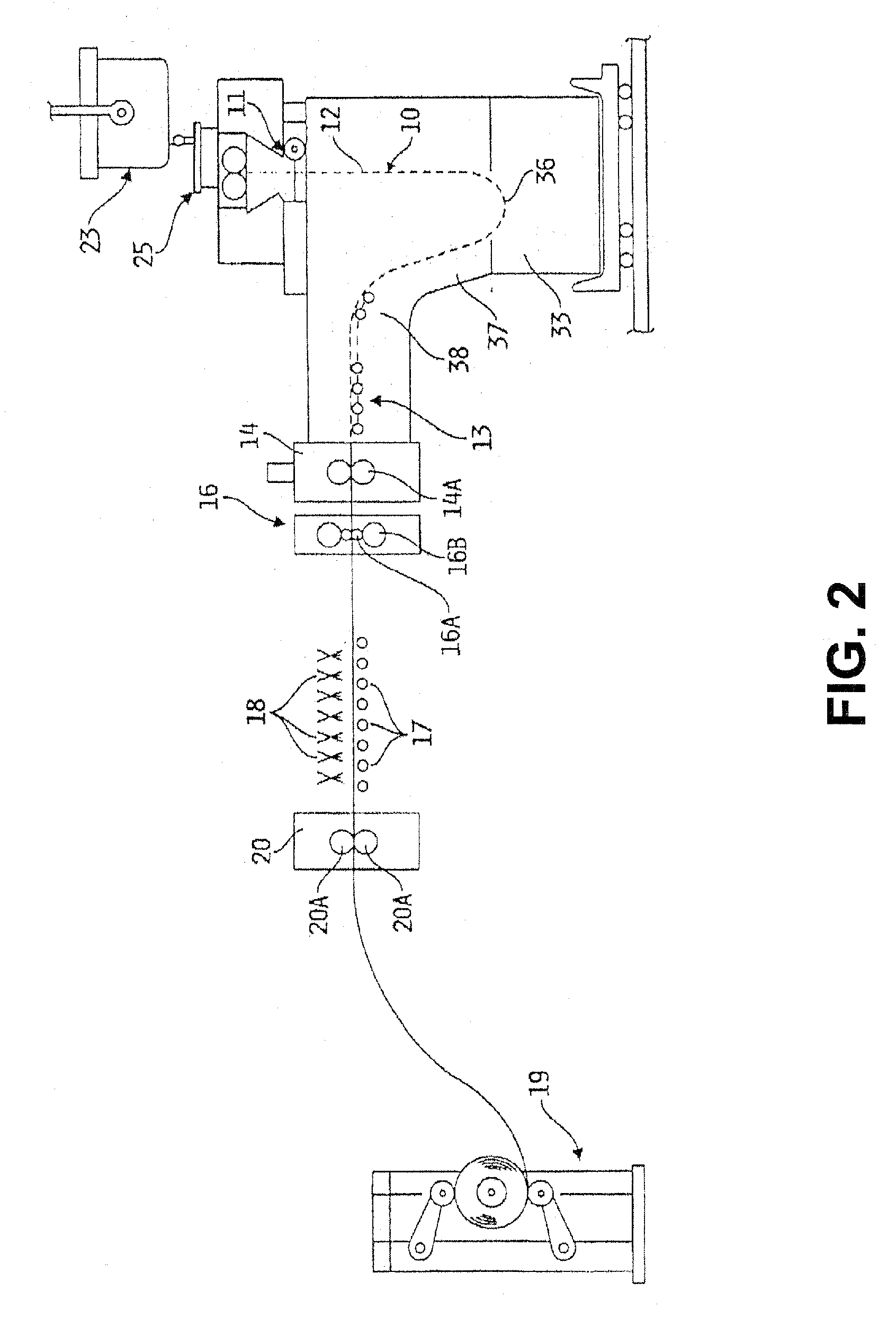
[0042]FIGS. 2 and 3 illustrate a twin roll continuous strip caster suitable to p...


PUM

PropertyMeasurementUnit
temperatureaaaaaaaaaa

Abstract

A method for making a thin cast strip with reduced meniscus marks includes assembling a pair of casting rolls laterally positioned to form a nip therebetween, preparing molten steel having a carbon content in the range of 0.01 to 0.3% by weight, a manganese content between 0.1 and 0.8% by weight, a silicon content between 0.05 and 0.5% by weight, a calcium content between 0.0008 and 0.004% by weight, an aluminum content between 2 and 500 ppm by weight, having a free oxygen content below about 50 ppm at 1600 ° C., forming a casting pool of the molten steel supported on casting surfaces of the casting rolls above the nip, and counter-rotating the casting rolls cause thin strip to be casted downwardly from the nip.

Description

[0001] This application is a continuation-in-part application of Ser. No. 11 / 419,684, filed May 22, 2006, which is a divisional application of Ser. No. 10 / 761,953 filed Jan. 21, 2004, now U.S. Pat. No. 7,048,033, which is a continuation-in-part application of application Ser. No. 10 / 243,699, filed Sep. 13, 2002, now abandoned, which claims priority to and the benefit of U.S. Provisional Patent Application No. 60 / 322,261, filed Sep. 14, 2001, the disclosures of which are expressly incorporated herein by reference.BACKGROUND OF THE INVENTION [0002] This invention relates to the casting of steel strip and particularly to casting of steel strip using roll casters. [0003] In a roll caster, molten metal is cooled on casting surfaces of at least one casting roll and formed into thin cast strip. In roll casting with a twin roll caster, molten metal is introduced between a pair of counter rotated casting rolls that are cooled. Steel shells solidify on the moving casting surfaces and are brou...

Claims


Application Information

Patent Timeline
Patent Type & Authority Applications(United States)
IPC IPC(8): B22D11/06
CPCB22D11/0622B22D11/1206B22D27/20C22C1/02C22C38/18C22C38/04C22C38/002C22C38/02C22C38/06C22C33/04B22D11/06C22C38/38
Inventor MAHAPATRA, RAMA BALLAVSOSINSKY, DAVID J.
Owner NUCOR CORP
Learn More