
Gaseous fuel and air mixing venturi device and method for carburetor

Inactive Publication Date: 2007-04-05
CONTINENTAL CONTROLS CORP
View PDF11 Cites 31 Cited by
  • Summary
  • Abstract
  • Description
  • Claims
  • Application Information

AI Technical Summary

Benefits of technology

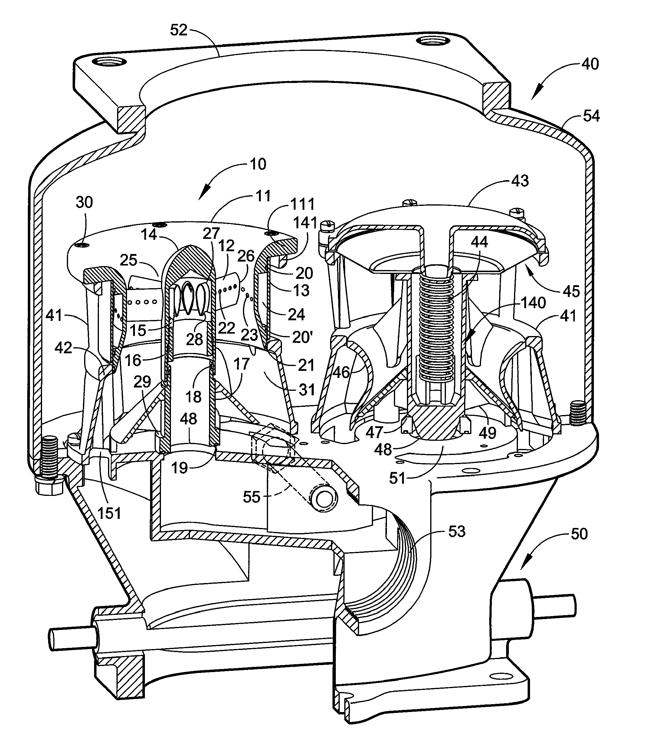
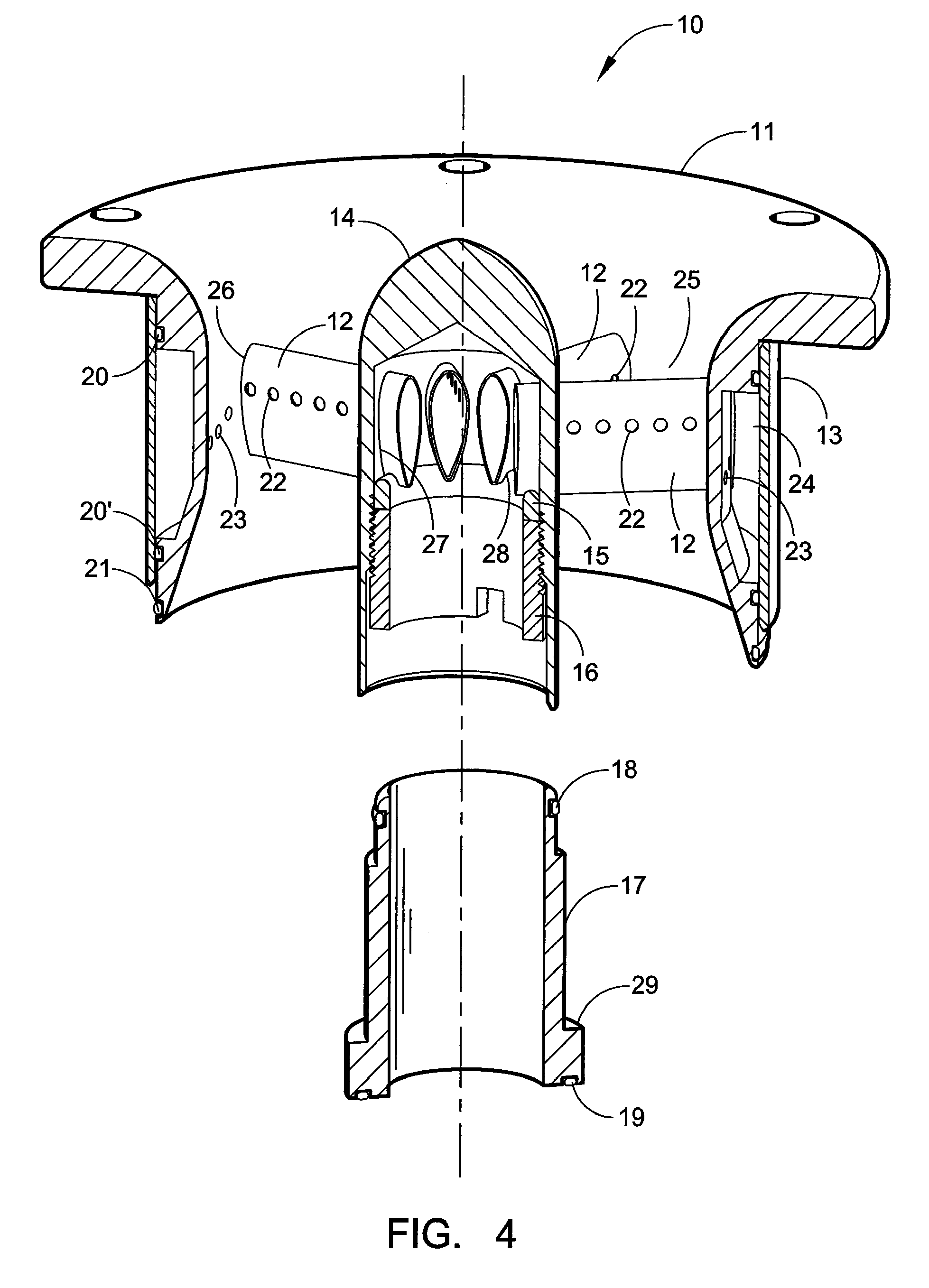
[0013] The venturi insert device replaces the conventional spring mass air / fuel mixing section of a gaseous fuel carburetor, such as a natural gas carburetor, and eliminates all moving parts in the air / fuel mixing section of the carburetor. The insert device in one embodiment is designed to maintain a near stoichiometric mixture throughout the operating range of the engine. Some applications, such as lean burn engines, require a venturi insert sized to run at an air / fuel ratio other than stoichiometric. Final corrections to the air / fuel ratio are made by the upstream air / fuel ratio controller. The venturi insert has a multitude of fuel inlet passages evenly dispersed throughout the low-pressure region of its throat. The fuel is more evenly distributed across the flow profile resulting in a more homogenous air / fuel mixture entering the engine.
[0015] The airflow and fuel flow area of the venturi insert can be modified to fit the application specifically and provide a multitude of sizing options for each model of carburetor. Alternatively the customer could simply install the correct size venturi insert into the existing carburetor. The venturi insert uses the existing mixture screw and butterfly throttle assembly of the carburetor. The cost savings for labor, materials, and down time are substantial. The venturi insert improves the performance of diaphragm operated carburetors used on internal combustion engines, by completely replacing the problematic spring mass, diaphragm actuator of existing gaseous fuel carburetors. Different venturi insert configurations are designed for specific models of carburetor such that the venturi insert device is relatively simple to install and does not require the user to make any changes to the existing fuel system plumbing. The various configurations may have significant differences in size and shape, but they all utilize a venturi air passage to draw fuel into the air stream. In an effort to improve the air and fuel mixing of existing carburetors, all configurations have a multitude of fuel inlet passages evenly dispersed throughout the low-pressure region of the venturi.

Problems solved by technology

This has the potential to create unstable engine performance due to interaction with the upstream pressure regulator or emissions control valve.
These new systems can respond very quickly and often create unstable interactions between the carburetor and the upstream fuel valve.
The diaphragm is typically an elastomer coated fabric and is susceptible to chemical and thermal degradation, rupture due to engine backfiring, abrasive damage, and the like.
The air / fuel mixing section of the carburetor also has sliding surfaces that are prone to wear.
Down time of an engine due to required maintenance in an industrial application, such as a pump on an oil pipeline, can result in the loss of thousands of dollars from lost production.
Another deficiency of known gaseous fuel carburetors is the limited ability to thoroughly mix the air and fuel together.
This makes it more difficult for the engine to completely burn all incoming fuel, which often results in higher exhaust emissions and a reduction in horsepower.
The limited number of existing gaseous fuel carburetor models and sizes may require the user to install a unit that is too large for the application.
A carburetor excessively large for an engine may cause starting troubles.
These mixers are not installed in the existing carburetor.
Instead, they replace the carburetor entirely, which often creates substantial installation difficulties and costs.
This requires major modifications to the engine's air intake system, which could result in thousands of dollars of lost production time.
Another major deficiency is that these mixers do not include a butterfly for controlling the air / fuel mixture to the engine.
Conventional retrofit difficulties increase significantly when the engine uses more than one carburetor, which is often the case.

Method used


Image

  • Gaseous fuel and air mixing venturi device and method for carburetor
  • Gaseous fuel and air mixing venturi device and method for carburetor
  • Gaseous fuel and air mixing venturi device and method for carburetor

Examples


Embodiment Construction

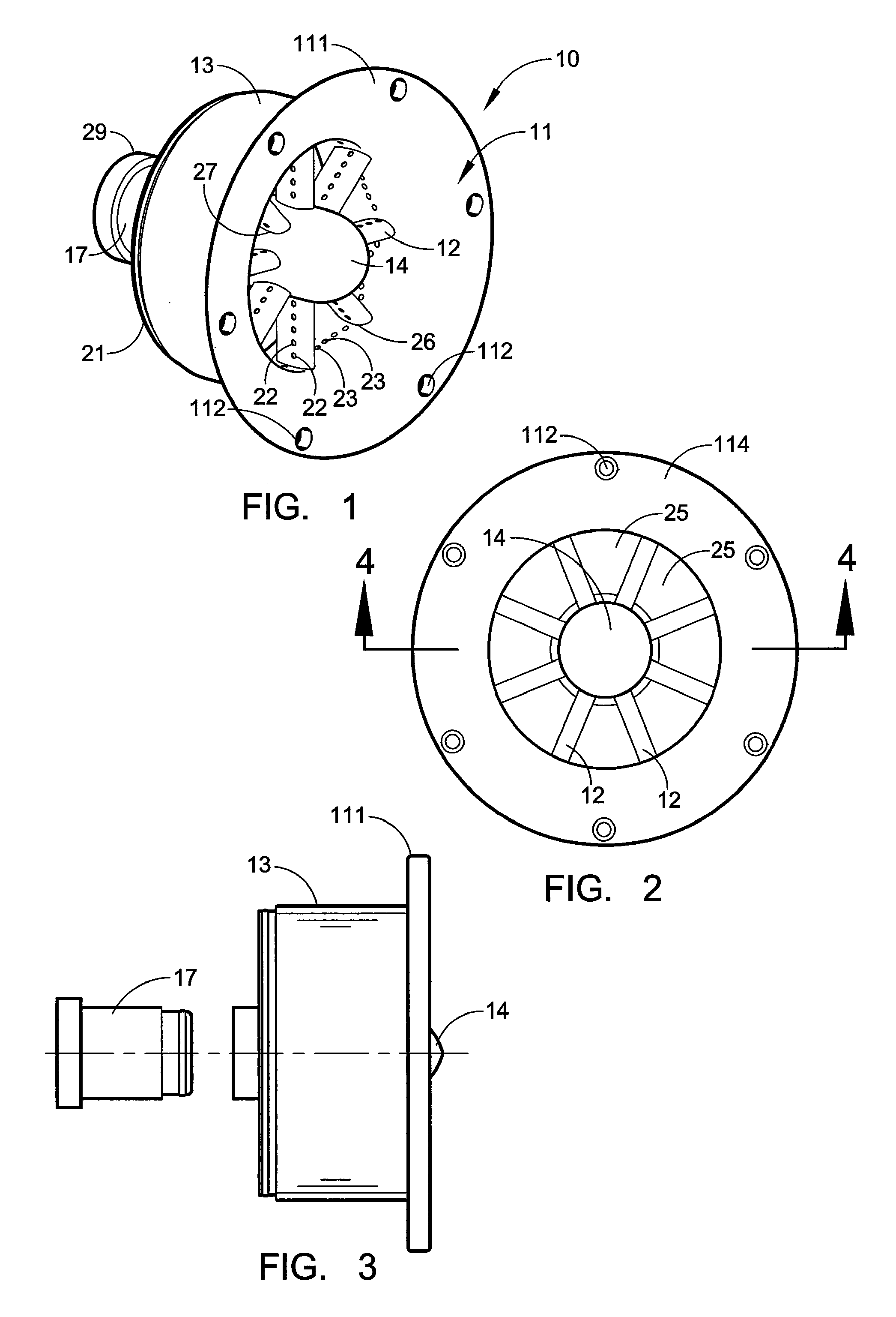
[0031] Certain embodiments as disclosed herein provide for a venturi insert device for mounting in a carburetor body, and a retrofit method for replacing an existing gaseous fuel and air mixing device in a carburetor with the venturi insert device.

[0032] After reading this description it will become apparent to one skilled in the art how to implement the invention in various alternative embodiments and alternative applications. However, although various embodiments of the present invention will be described herein, it is understood that these embodiments are presented by way of example only, and not limitation. As such, this detailed description of various alternative embodiments should not be construed to limit the scope or breadth of the present invention as set forth in the appended claims.

[0033] FIGS. 1 to 4 of the drawings illustrate a gaseous air and fuel mixing venturi insert device 10 according to an exemplary embodiment of the invention for replacing a conventional fuel a...


PUM

PropertyMeasurementUnit
Diameteraaaaaaaaaa
Lengthaaaaaaaaaa
Areaaaaaaaaaaa

Abstract

A gaseous fuel and air mixing venturi device adapted for retrofitting in a carburetor has a venturi body with a passage for air flow through the body, the passage having a throat of reduced cross-sectional area. The body has an axial fuel inlet port at a first end and fuel supply ports connected to the fuel inlet port and spaced around the throat for supplying fuel to the air flow passage for mixing with air flowing through the passage. The first end of the venturi body has mating seating formations for seating against corresponding seating surfaces of a gaseous fuel carburetor after removal of a spring mass air / fuel mixing section, and a fastener mechanism for releasably securing the venturi body in the carburetor, with the fuel supply port of the carburetor connected to the fuel inlet port of the venturi body.

Description

RELATED APPLICATION [0001] The present application claims priority to co-pending U.S. provisional patent application Ser. No. 60 / 722,113 entitled GASEOUS FUEL AND AIR MIXING ADAPTER DEVICE FOR CARBURETOR of concurrent ownership, filed on Sep. 30, 2005, which is incorporated herein by reference in its entirety.BACKGROUND [0002] 1. Field of the Invention [0003] This invention relates generally to devices for mixing gaseous fuel and air in the correct proportions for combustion in a gas engine, and is particularly concerned with a venturi mixing device for replacing the spring mass, diaphragm actuator of existing gaseous fuel carburetors for natural gas engines and the like, and with a method of retrofitting a carburetor with such a device. [0004] 2. Related Art [0005] The majority of gaseous fuel carburetors for internal combustion engines have an air / fuel mixing section which is comprised of a spring mass system. This has the potential to create unstable engine performance due to int...

Claims


Application Information

Patent Timeline
IPC IPC(8): F02M21/04
CPCY02T10/32F02M21/047F02M21/029F02M21/042Y10S261/12Y02T10/30
Inventor YATES, KRISTIAN W.
Owner CONTINENTAL CONTROLS CORP
Learn More