
Flat panel display module

a display module and flat panel technology, applied in the direction of instruments, portable computer details, electric apparatus casings/cabinets/drawers, etc., can solve the problems of relative difficulty in providing high precision distance between adjacent two retention ribs, and are susceptible to breakage, so as to increase the stability of the combination of display panels and tighten the clamping effect of the display panel

Active Publication Date: 2007-03-22
AU OPTRONICS CORP
View PDF7 Cites 45 Cited by
  • Summary
  • Abstract
  • Description
  • Claims
  • Application Information

AI Technical Summary

Benefits of technology

[0009] One object of the present invention is to provide a flat panel display module including a plurality of the elastic pieces that is disposed at the side of a plastic frame to clamp the display panel to prevent its wobbling in the gap between the display panel and the plastic frame, or between the plastic frame and a front frame.
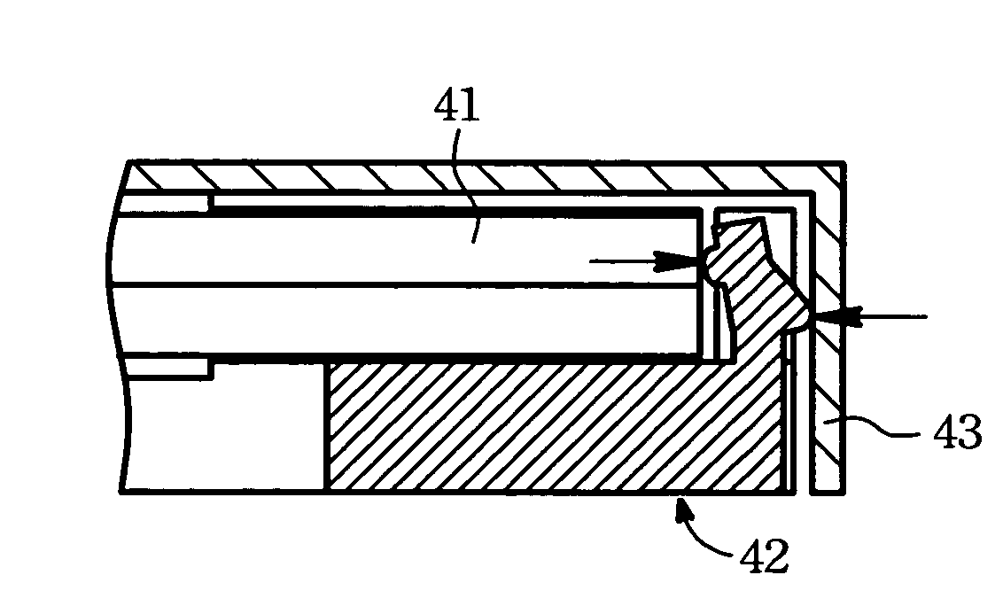
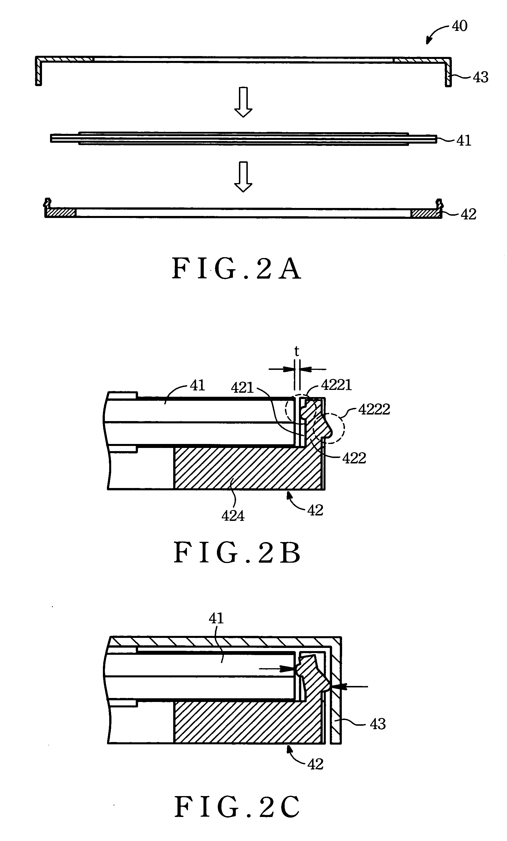
[0011] The display panel may be a liquid crystal display panel or an organic electroluminescent display panel. Several preferred embodiments illustrate how to increase the stability for the combination of the display panel and the frames. The elastic piece of the first frame has a protrusion projecting outward. Once the second frame presses the protrusion, the elastic piece is curved to contact the side of the display panel. In addition, the inner side of the elastic piece may have another protrusion to clamp the display panel more tightly.

Problems solved by technology

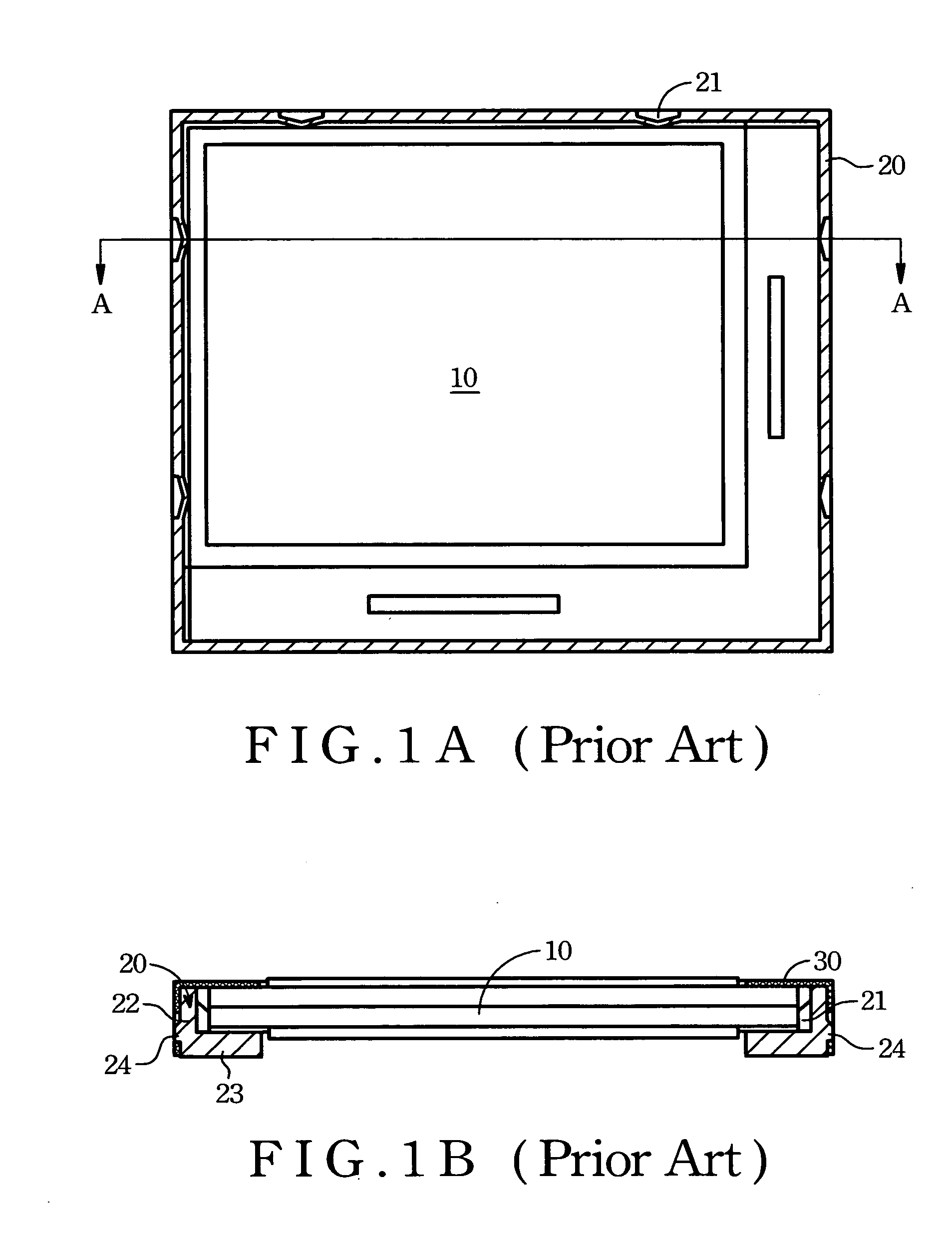
However, it is relatively difficult to provide high precision distance between the adjacent two retention ribs 21.
In addition, the retention ribs 21 are susceptible to break and eventually lead to clearance between the LCD panel 10 and the plastic frame body 20.

Method used


Image

  • Flat panel display module
  • Flat panel display module
  • Flat panel display module

Examples


Embodiment Construction

[0027]FIG. 2A shows a flat panel display module 40, includes a display panel 41, a first frame 42 and a second frame 43. The display panel 41 is clamped through the second frame 43 assembled on the first frame 42. As shown in arrows, the display panel 41 is put into the first frame 42, and then is covered by the second frame 43. The second frame 43 is assembled on the first frame 42 to fix the display panel 41 to construct the flat panel display module 40.

[0028] Referring to FIG. 2B, the first frame 42, of which the side-looking is shaped roughly “L”, includes an elastic piece 422 and a flat base 424 connected to a sidewall of the first frame 42 for supporting the display panel 40. The root portion of the elastic piece 422 is fixed on the flat base 424. The display panel 41 is supported by the flat base 424 and the side of the display panel 41 is opposite to the inner side of the elastic piece 422. For assembly, the top of the elastic piece 422 is pulled outward first, and returned...


PUM


Abstract

A flat panel display module comprises a display panel clamped by a first frame and a second frame structure. The first frame includes a sidewall and an elastic piece, wherein the sidewall encloses the display panel and has a breach. The elastic piece is disposed in the breach of the sidewall. The second frame can be assembled on the first frame. The second frame presses the elastic piece so that the elastic piece is curved to contact a side of the display panel.

Description

[0001] This application claims the benefit of Taiwan Patent Application Serial No. 094132145, filed Sep. 16, 2005, the subject matter of which is incorporated herein by reference. BACKGROUND OF THE INVENTION [0002] (1) Field of the Invention [0003] The present invention relates to a flat panel display module, and more specifically to a flat panel display module including a display panel and a frame that is capable of tightly clamping the display panel. [0004] (2) Description of the Prior Art [0005] The LCD technology is widely used in display monitors, mobile phones, digital cameras, digital video cams, personal digital assistances (PDA), and many other electronic devices. Thus, for the display operation, a LCD panel plays an important role. A backlight unit is usually required to illuminate the LCD panel since the LCD panel is a non-self-luminous device. A conventional LCM (liquid crystal module) includes a front frame part, a plastic frame body and a rear frame part, which coopera...

Claims


Application Information

Patent Timeline
IPC IPC(8): G06F1/16G02F1/1333
CPCG02F1/133308G02F2001/133317G02F2201/465G06F2200/1612G06F1/1601G06F1/1613G06F1/1637G02F2201/503G02F1/133317
Inventor LO, CHI-CHUNGWU, CHIA-JUNG
Owner AU OPTRONICS CORP
Learn More