
Quick detection of signaling in a wireless communication system

a wireless communication system and signal detection technology, applied in the field of communication, can solve the problems of reducing the available battery power, wasting battery power, and wasting battery power, so as to prolong the battery standby time, reduce the warm-up time, and reduce the power consumption of the battery

Active Publication Date: 2007-03-15
QUALCOMM INC
View PDF8 Cites 88 Cited by
  • Summary
  • Abstract
  • Description
  • Claims
  • Application Information

AI Technical Summary

Benefits of technology

[0010] Techniques for performing quick frequency tracking (QFT), quick time tracking (QTT), and non-causal pilot filtering (NCP) to detect signaling (e.g., paging indicators) transmitted sporadically in a wireless communication system are described herein. These techniques may be used by a wireless device to (1) reduce warm-up time per awake interval during DRX operation in the idle mode, (2) reduce battery power consumption and extend battery standby time, and (3) provide improved detection performance under certain operating scenarios. These techniques may be used for signaling sent from one antenna with no transmit diversity and for signaling sent from two antennas with space-time transmit diversity (STTD). Any one, any combination, or all three techniques may be used for signaling detection.

Problems solved by technology

In the idle mode, the wireless device continues to consume power to sustain circuitry needed to monitor the signals transmitted by the base stations in the system.
Power consumption by the wireless device in the idle mode decreases the available battery power, which shortens the standby time between battery recharges and the talk time when a call is placed or received.

Method used


Image

  • Quick detection of signaling in a wireless communication system
  • Quick detection of signaling in a wireless communication system
  • Quick detection of signaling in a wireless communication system

Examples


Embodiment Construction

[0034] The word “exemplary” is used herein to mean “serving as an example, instance, or illustration.” Any embodiment or design described herein as “exemplary” is not necessarily to be construed as preferred or advantageous over other embodiments or designs.

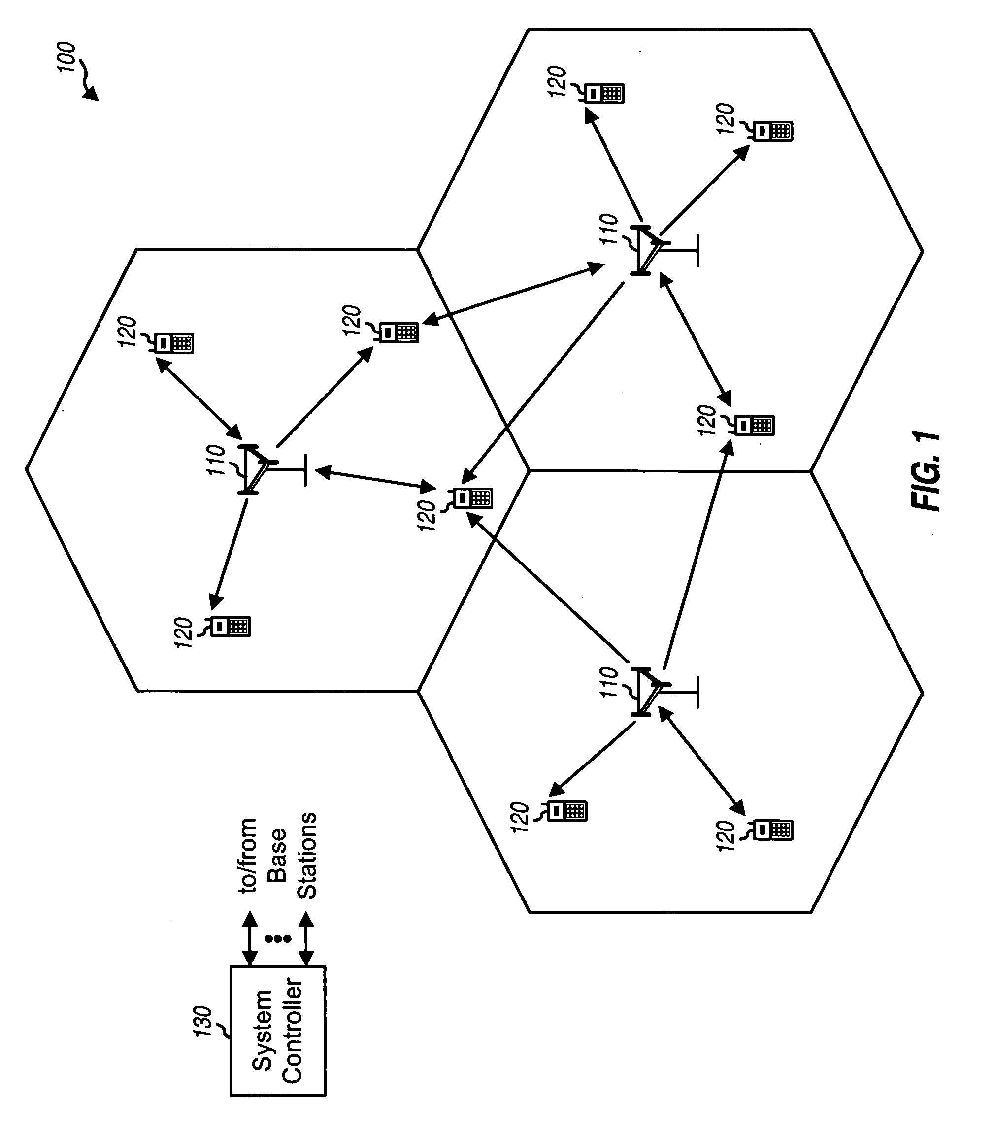
[0035]FIG. 1 shows a wireless communication system 100 with multiple base stations 110 and multiple wireless devices 120. A base station is generally a fixed station that communicates with the wireless devices and may also be called a Node B, a base transceiver subsystem (BTS), an access point, or some other terminology. Wireless devices 120 may be dispersed throughout the system. A wireless device may be fixed or mobile and may also be called a mobile station, a user equipment, a terminal, a subscriber unit, or some other terminology. A wireless device may communicate with zero, one, or multiple base stations on the downlink and / or uplink at any given moment. The downlink (or forward link) refers to the communication link from ...


PUM


Abstract

Quick frequency tracking (QFT), quick time tracking (QTT), and non-causal pilot filtering (NCP) are used to detect sporadically transmitted signaling, e.g., paging indicators. For QFT, multiple hypothesized frequency errors are applied to an input signal to obtain multiple rotated signals. The energies of the rotated signals are computed. The hypothesized frequency error with the largest energy is provided as a frequency error estimate. For QTT, coherent accumulation is performed on the input signal for a first set of time offsets, e.g., early, on-time, and late. Interpolation, energy computation, and non-coherent accumulation are then performed to obtain a timing error estimate with higher time resolution. For NCP, pilot symbols are filtered with a non-causal filter to obtain pilot estimates for one antenna for non-STTD and for two antennas for STTD. The frequency and timing error estimates and the pilot estimates are used to detect the signaling.

Description

BACKGROUND [0001] I. Field [0002] The present invention relates to communication, and more particularly to techniques for detecting signaling transmitted sporadically in a wireless communication system. [0003] II. Background [0004] A wireless device (e.g., a cellular phone) in a wireless communication system may be designed to operate in one of several modes, such as “active” and “idle”, at any given moment. In the active mode, the wireless device can actively exchange data with one or more base stations in the system, e.g., for a voice or data call. In the idle mode, the wireless device may monitor a paging channel (PCH) for messages applicable to the device. Such messages may include page messages that alert the wireless device to the presence of an incoming call and overhead messages that carry system information and other information for the wireless device. [0005] In the idle mode, the wireless device continues to consume power to sustain circuitry needed to monitor the signals...

Claims


Application Information

Patent Timeline
IPC IPC(8): H04B1/16H04B1/38H04M1/00
CPCH04B1/7085H04B2201/70709H04L27/2278H04W52/0229H04L2027/0034H04L2027/0065H04L2027/003Y02D30/70
Inventor SUBRAHMANYA, PARVATHANATHANSHESHADRI, THEJASWI BHARADWAJ MADAPUSHICHAWLA, VIVEK
Owner QUALCOMM INC
Learn More