
Induction heating roller device, heating roller for induction heating roller device, fixing apparatus and image forming apparatus

a technology of heating roller and heating roller, which is applied in the direction of electric/magnetic/electromagnetic heating, dc-ac conversion without reversal, instruments, etc., can solve the problems of insufficient thermal capacity, inability to achieve high electric power transmitting efficiency, and inability to shorten the warm-up time interval. , to achieve the effect of shortening the warm-up time interval

Inactive Publication Date: 2005-01-25
HARISON TOSHIBA LIGHTING CORP
View PDF8 Cites 23 Cited by
  • Summary
  • Abstract
  • Description
  • Claims
  • Application Information

AI Technical Summary

Benefits of technology

It is therefore an object of the present invention to provide an induction heating roller device and a heating roller for the induction heating roller device, and a fixing apparatus and an image forming apparatus, using such component parts, which are able to obtain a high electric power transmitting efficiency.
Thus, the present invention allows the induction heating roller device of the first aspect of the present invention or the induction heating roller device of the ninth aspect of the present invention to include the heating roller to provide the image forming apparatus which is able to shorten the warm-up time interval.

Problems solved by technology

Such a technology encounters an issue such as a prolonged warm-up time or an insufficient thermal capacity.
However, the Related Art 3 encounters an issue wherein a warm-up time can not be so shortened as expected.
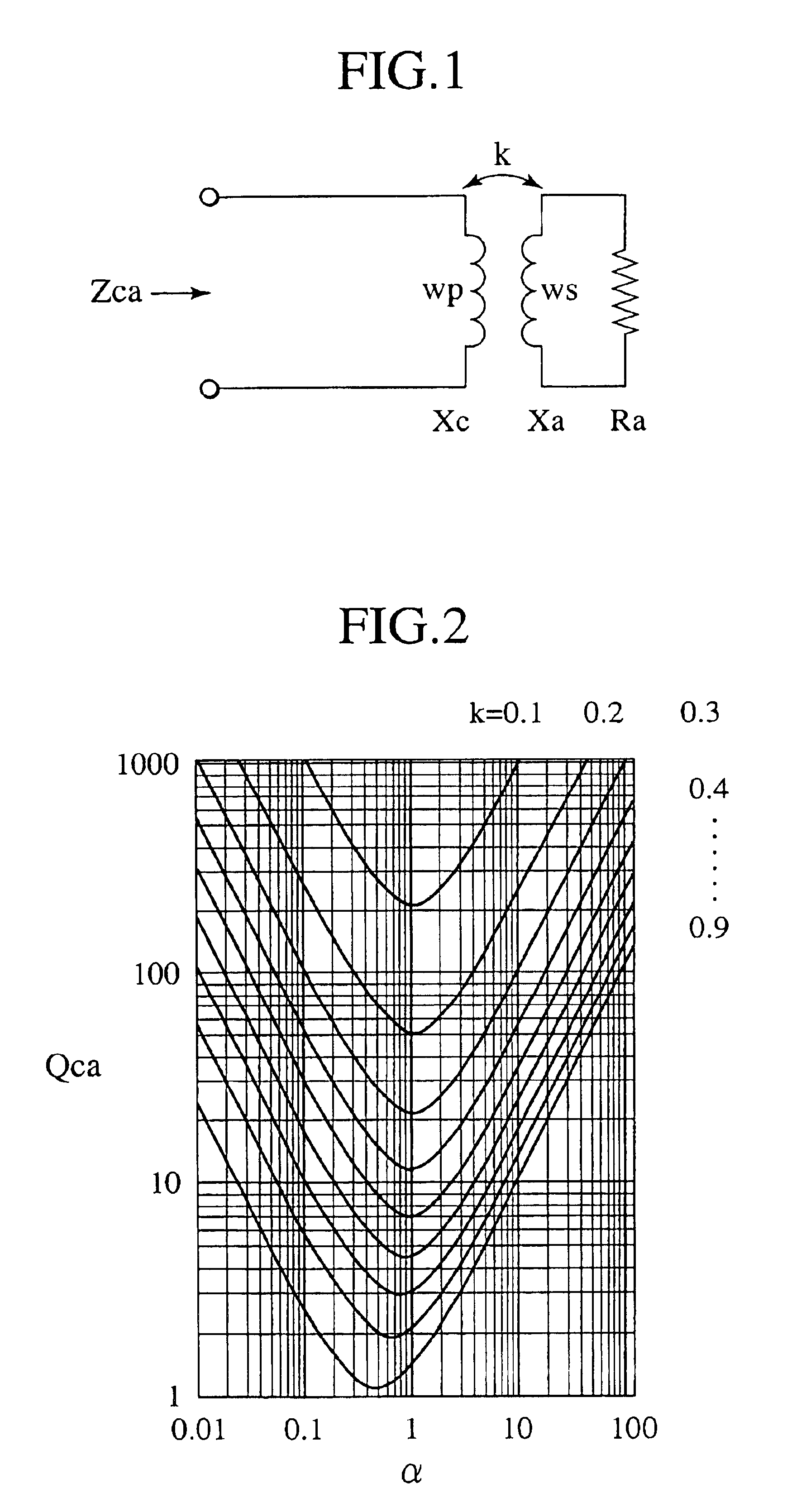
Upon considerable research and study conducted by the inventor, such an issue is deemed to originate from the resistance value of the secondary coil formed in the heating roller, which is not supervised.
In the Related Art 3, further, with the use of such a low frequency ranging from 20 to 100 kHz that is obtained in an IGBT inverter that is used in cooking equipments such as an induction heating type cooker or range, it is difficult for a high electric power transmitting efficiency to be obtained.

Method used


Image

  • Induction heating roller device, heating roller for induction heating roller device, fixing apparatus and image forming apparatus
  • Induction heating roller device, heating roller for induction heating roller device, fixing apparatus and image forming apparatus
  • Induction heating roller device, heating roller for induction heating roller device, fixing apparatus and image forming apparatus

Examples


Embodiment Construction

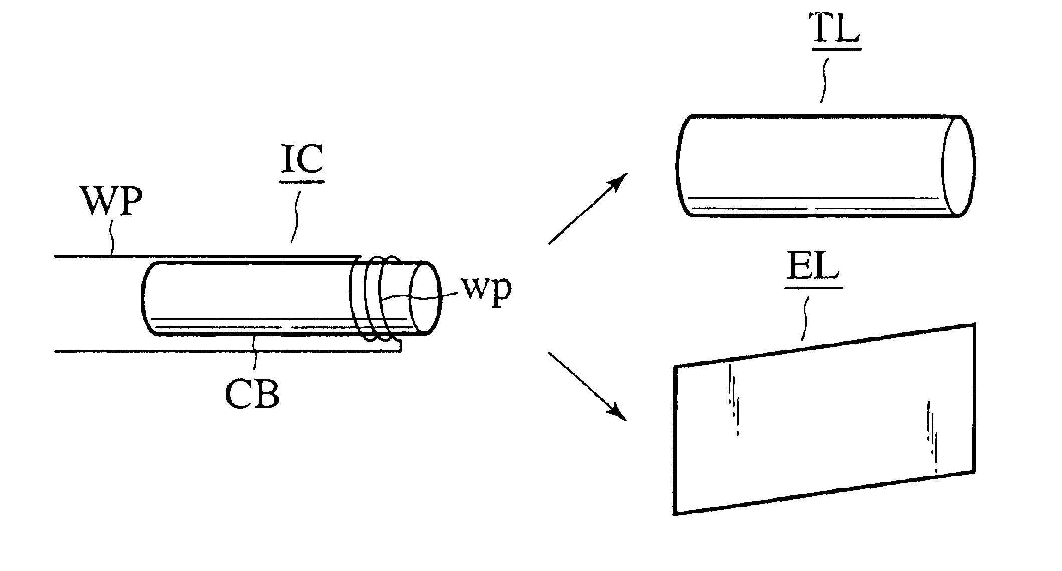
To describe the present invention more in detail, an induction heating roller device of a preferred embodiment according to the present invention will be described below in detail in conjunction with FIGS. 8 to 10, wherein FIG. 8 is an exploded view, partly in cut away, of the induction heating roller device of a first preferred embodiment according to the present invention. FIG. 9 is an enlarged transverse cross sectional view of an induction heating roller. FIG. 10 is an enlarged longitudinal cross sectional view of an essential part of the heating roller shown in FIG. 9.

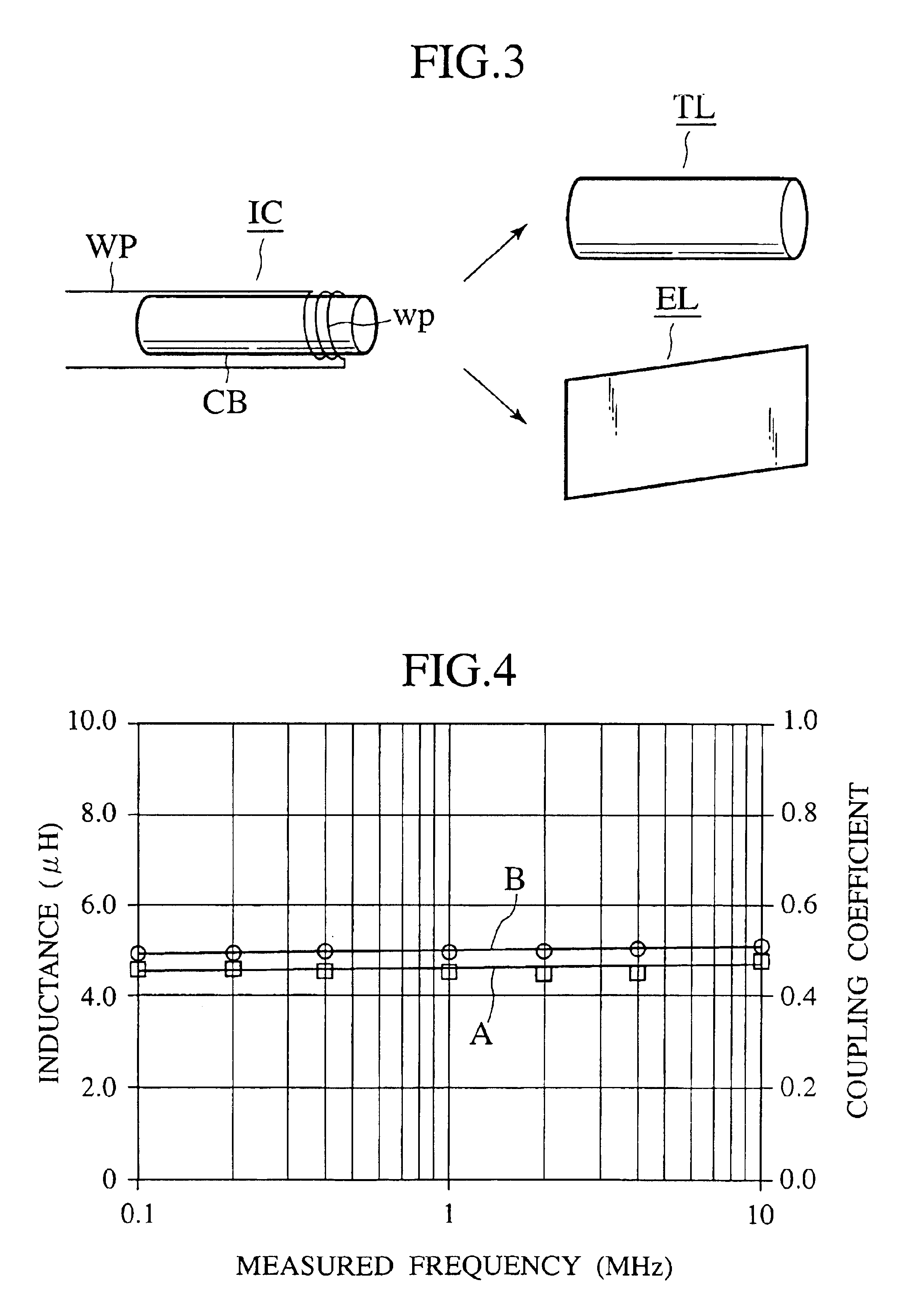
In FIGS. 8 to 10, like component parts bear the same reference numerals as those used in FIG. 3 and a detailed description of the same is herein omitted for the sake of simplicity. In the presently filed preferred embodiment, the induction coil unit device IC includes a primary coil composed of a plurality of primary coil components wp, and the heating roller TR includes a secondary coil composed of a plurality of...


PUM


Abstract

An induction heating roller, a fixing apparatus and an image forming apparatus are disclosed as including a heating roller (TR) comprised of a hollow roller base body (BB), composed of electrically insulating material, and a plurality of secondary coil components (ws), composed of closed circuits, respectively, which are formed over the roller base body. The heating roller (TR) internally receives an induction coil unit (IC) including a primary coil (wp) which is coupled with the secondary coils in a core-less transformer coupling relationship. The secondary coil components (ws) of the heating roller (TR) have a secondary resistance value (Ra) which is nearly equal to a secondary reactance (Xa), i.e. in case of Ra / Xa=α, a formula is expressed as 0.1<α<10. Further, the primary coil (wp) of the induction coil unit (IC) is comprised of a plurality of coil components which are connected between a wire pair (WP) in parallel to one another.

Description

BACKGROUND OF THE INVENTIONThe present invention relates to an induction heating roller device, a heating roller for the induction heating roller, a fixing apparatus and an image forming apparatus.A heating roller, which includes a thermal source composed of a halogen lamp, has heretofore been employed to thermally fix toner image onto record medium. Such a technology encounters an issue such as a prolonged warm-up time or an insufficient thermal capacity. To address this issue, considerable research and development work has been undertaken in the past to commercially apply an induction heating technology.Japanese Patent Publication NO. 2000-215974 discloses an excitation coil located in close proximity to an object body to be heated for causing induction current to flow through the object body, with the excitation coil including a coil wire material wound in a plane and deformed in a shape to cope with a curved wall of the object body while a magnetic core is located in a position ...

Claims


Application Information

Patent Timeline
IPC IPC(8): G03G15/20H05B6/14H02M7/48H05B6/04H05B6/06
CPCH05B6/145G03G15/2053
Inventor YOKOZEKI, ICHIROSHIMOKAWA, TEIJIKAWAMURA, MASAAKI
Owner HARISON TOSHIBA LIGHTING CORP
Learn More