
Method of making an electroplated interconnection wire of a composite of metal and carbon nanotubes

a technology of carbon nanotubes and interconnection wires, which is applied in the direction of printed circuit manufacturing, superimposed coating process, coating, etc., can solve the problem that the method is not applicable on a substrate with a large surface area, and achieves the effect of reducing the electromigration resistance of copper, increasing current density, and high young's modulus

Inactive Publication Date: 2007-03-15
IND TECH RES INST
View PDF9 Cites 41 Cited by
  • Summary
  • Abstract
  • Description
  • Claims
  • Application Information

AI Technical Summary

Benefits of technology

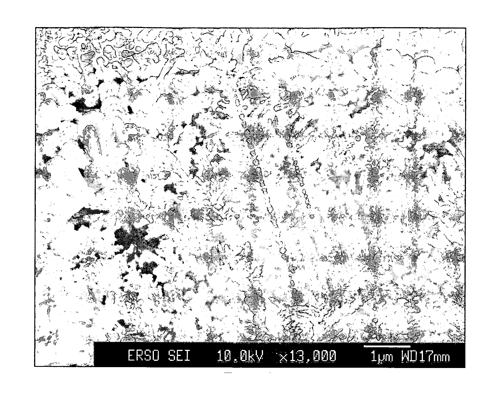
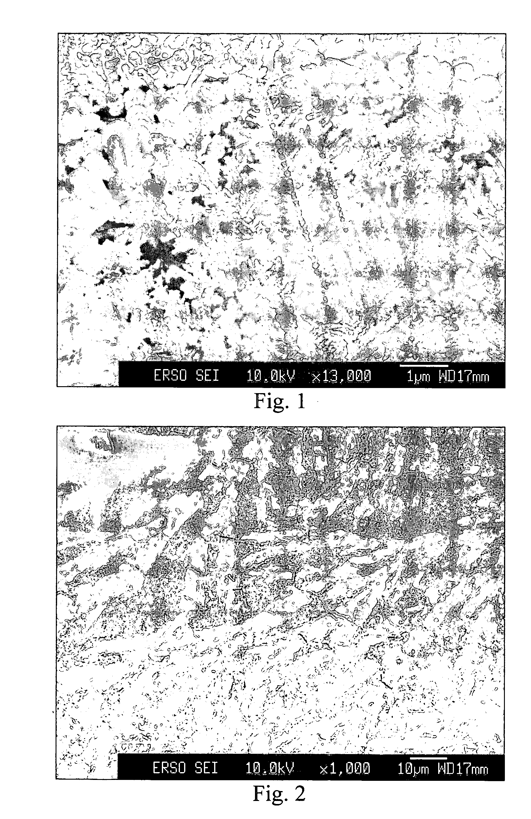
[0004] A primary objective of the present invention is to provide a method for forming an electroplated interconnection wire of a composite of carbon nanotubes and a metal (e.g. copper). Said electroplated interconnection wire, when used as a conductive channel, has an increased current density and a reduced electromigration resistance of copper. Furthermore, since carbon nanotubes have a high Young's modulus (1 Tpa ˜1.24 TPa), the electroplated interconnection wire of a composite of carbon nanotubes and a metal formed according to the method of the present invention has improved mechanical strength in comparison with a copper wire. When an interconnection wire formed between devices on a flexible substrate, it must have a higher ductility and a higher strength. The electroplated interconnection wire of a composite of carbon nanotubes and a metal formed according to the method of the present invention is very suitable for use as an interconnection wire on the flexible substrate.

Problems solved by technology

However, this method is not applicable on a substrate with a large surface area.

Method used


Image

  • Method of making an electroplated interconnection wire of a composite of metal and carbon nanotubes
  • Method of making an electroplated interconnection wire of a composite of metal and carbon nanotubes

Examples


Embodiment Construction

[0012] The present invention provides a method for forming an interconnection wire on a substrate having a large surface area, wherein said interconnection wire is a composite material of carbon nanotubes and a metal (e.g. copper). The invented method is applicable on forming an interconnection wire on a blank substrate, or forming an interconnection wire which connects devices provided on a substrate. A method according to the present invention comprises, firstly, forming a conductive baseline as an electroplating base on a surface of said substrate; and electroplating an interconnection wire of a composite material of carbon nanotubes and a metal on said conductive baseline. According to the material of said conductive baseline, the present invention can be implemented in two different manners. An embodiment using a flexible substrate will be described to illustrate the present invention.

[0013] On a flexible substrate formed of a polymer (e.g. polyimide), a metal (e.g. copper) ba...


PUM

PropertyMeasurementUnit
timeaaaaaaaaaa
current densityaaaaaaaaaa
temperatureaaaaaaaaaa

Abstract

Method of making an electroplated interconnection wire of a composite of metal and carbon nanotubes is disclosed, including electroplating a substrate having a conductive baseline on a surface thereof in an electroplating bath containing a metal ion and carbon nanotubes, so that an electroplated interconnection wire of a composite of the metal and carbon nanotubes is formed on the conductive baseline. Alternatively, a method of the present invention includes preparing a dispersion of carbon nanotubes dispersed in an organic solvent, printing a baseline with the dispersion on a surface of a substrate, evaporating the organic solvent to obtain a conductive baseline, and electroplating the surface in an electroplating bath containing a metal ion, so that an electroplated interconnection wire of a composite of the metal and carbon nanotubes is formed on the conductive baseline.

Description

FIELD OF THE INVENTION [0001] The present invention relates to a method for forming an electroplated interconnection wire of a composite of metal and carbon nanotubes, particularly a method for forming an electroplated interconnection wire of a composite of copper metal and carbon nanotubes. BACKGROUND OF THE INVENTION [0002] U.S. Pat. No. 6,709,562 B1 discloses a method for producing a sub-micron interconnection structure on an integrated circuit chip, which comprises forming an insulation material on a substrate, forming trenches in said insulation by a photolithography technique; forming a conductive layer as an electroplating base on said insulation material; electroplating a seamless conductor in an electroplating bath containing copper ions and additives; and removing the electroplated conductor layer outside the trenches by polishing. The disclosure of said patent is incorporated herein by reference. [0003] U.S. Pat. No. 5,916,642 discloses a method of encapsulating a materia...

Claims


Application Information

Patent Timeline
Patent Type & Authority Applications(United States)
IPC IPC(8): C25D1/04
CPCC25D3/38C25D5/54C25D5/02C25D5/56
Inventor LO, PO-YUANWEI, JUNG-HUACHEN, BAE-HORNGCHIANG, JIH-SHUNHWANG, CHIAN-LIANGKAO, MING-JER
Owner IND TECH RES INST
Learn More