
Apparatus for Producing Dental Impressions

a technology for dental impressions and apparatuses, applied in dental prosthetics, medical science, dentistry, etc., can solve the problems of defective impressions, saliva, blood, time-consuming, stressful, etc., and achieve the effect of increasing the stability of the tray body

Inactive Publication Date: 2007-03-08
NEUSCHAFER GERD
View PDF7 Cites 70 Cited by
  • Summary
  • Abstract
  • Description
  • Claims
  • Application Information

AI Technical Summary

Benefits of technology

[0009] With the novel apparatus, it is possible to effectively produce dental correction impressions with an apparatus which may be easily handled. The novel injection correction tray may be handled in a similar way as known trays which simplifies usage of the novel apparatus for the user. The novel apparatus does not require separate means or steps for producing an injection channel. The injection channel is produced by the protrusion being part of the bottom plate or being connected thereto.
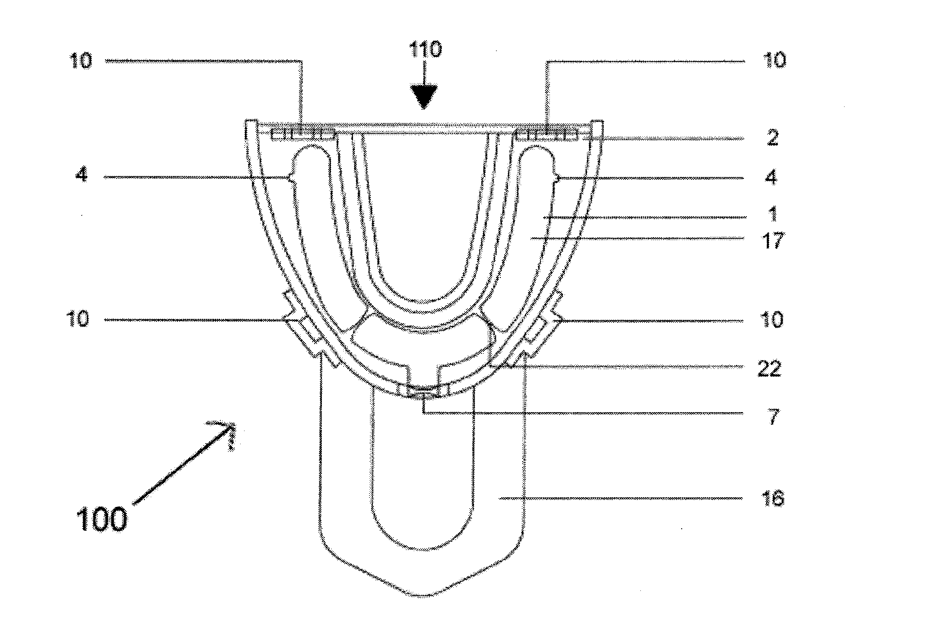
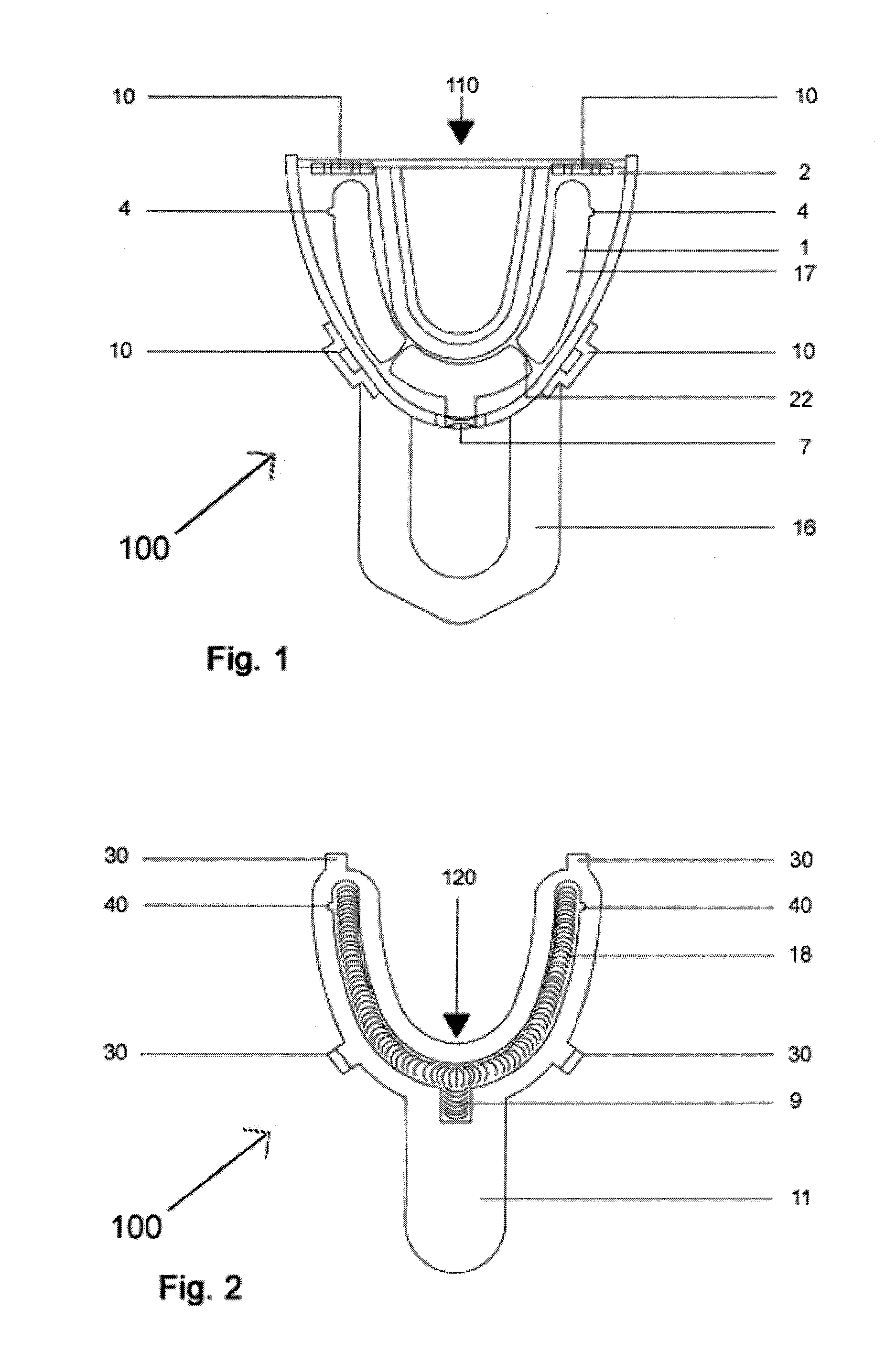
[0011] The bottom plate at its top side facing the bottom opening of the tray includes a protrusion being designed and arranged to protrude into the interior of the tray when the bottom plate is connected to the tray. In case the bottom plate is designed as a reversible bottom plate, meaning it can be connected to the tray in two different positions, its opposing bottom side is designed to be substantially plain. During production of the initial impression, the protrusion serves as a placeholder to form a free injection channel through which the correction impression material is later pressed into the tray during the second impression step, meaning the correction impression step. In other words, the protrusion (or the profile) of the bottom plate prevents initial impression material from entering this region. Generally, the shape of the protrusion approximately corresponds to the shape of the arc of the tray. Preferably, the protrusion has an inverted U-shaped or V-shaped cross section as seen when the top surface of the bottom place faces in an upward direction. It is also possible to realize the so called curve of Spee and the curve of Wilson in the design of the protrusion, and to design it to diminish in a way to reduce the required opening angle of the mouth.
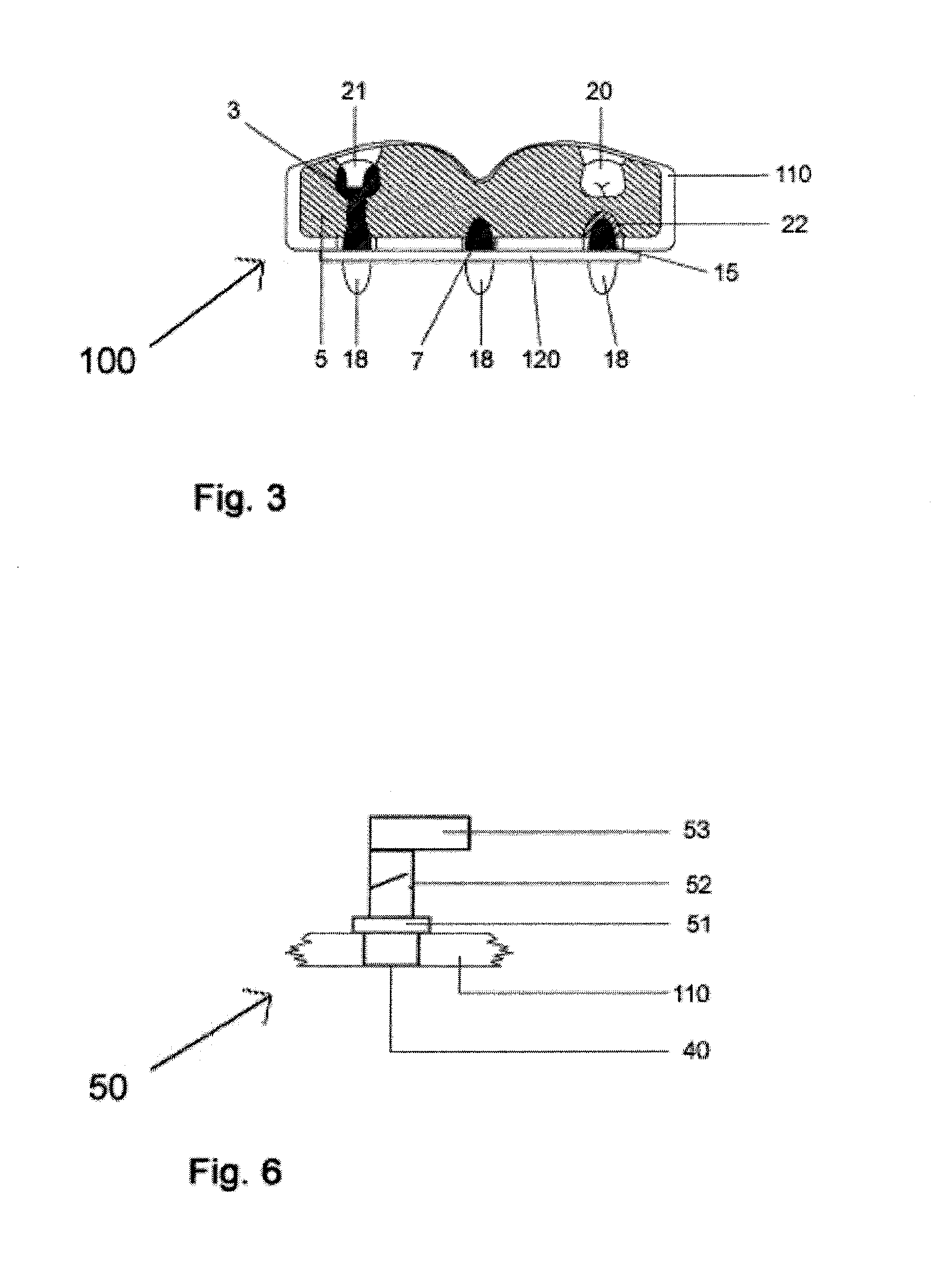
[0019] The injection opening may be designed to be conical to improve introduction of correction impression material into the injection channel. In this way, introduction of correction impression material is simplified by an improved adaptation of an injection needle to be connected to the injection channel. When using outlet valves for producing negative pressure, this design of the injection openings results in the injection openings being closed in an air-sealed way.
[0033] To simplify introduction of correction impression mass into the interior of the injection correction impression tray, especially when using the tray for making an impression of the upper jaw, it makes sense to arrange the injection inlet in the mesial wall of the tray. Such an embodiment of the tray may also be called a frontal injection correction impression tray. The bottom opening is enlarged to extend to the mesial bottom of the tray and to the mesial wall of the tray such that it forms a frontal injection opening. In a corresponding way, the protrusion of the bottom plate is enlarged in a congruent way to the mesial wall of the tray. The mesial portion of the protrusion is designed such that it closes the opening of the mesial wall of the tray.
[0035] The bottom plate may also be designed as a counter jaw impression bottom plate including a chamber for containing impression material for producing an impression of the counter jaw of the patient. In this way, it is possible to produce impressions of both jaws of the patient with one apparatus. For this purpose, the counter jaw bottom plate is designed such that it may be connected to the body of the tray in a reversible manner.
[0039] To increase stability of the body of the tray, the tray may include one or more stiffening elements. The stiffening elements are designed to connect the inner side and the outer side of the bottom opening. They protrude into the interior of the tray through the bottom opening at a suitable location. Their design and arrangement corresponds to the cross section of the protrusion at this location. In this way, the stiffening elements also serve to support the protrusion.

Problems solved by technology

The known apparatus and method conducted therewith may lead to defective impressions due to saliva, blood, air, turbulences and other anatomic influences such as the tongue, the cheek bands and so forth.
Such defects may result in the necessity of having to repeat the production of the impression or to insufficient prosthetic results.
Thus, the known method is time consuming, stressful, expensive and takes a lot of work.

Method used


Image

  • Apparatus for Producing Dental Impressions
  • Apparatus for Producing Dental Impressions
  • Apparatus for Producing Dental Impressions

Examples


Embodiment Construction

[0048] Referring now in greater detail to the drawings, FIGS. 1 to 3 illustrate a first exemplary embodiment of the novel apparatus 100 for producing dental impressions. The illustrated exemplary embodiment of the novel apparatus 100 is used for producing an impression of a tooth 21 being contained in the upper jaw of a patient. However, the apparatus 100 may also be used for taking impressions of the lower jaw or of both jaws. The apparatus 100 includes an injection correction impression tray 110 illustrated in FIG. 1 and a bottom plate 120 illustrated in FIG. 2. The mounted position of the bottom plate 120 at the injection correction impression tray 110 is illustrated in FIG. 3.

[0049] The injection correction impression tray 110 has a body 2 and a tray handle 16. The body 2 includes side walls and a bottom side which generally form the interior 17 of the injection correction impression tray 110 which serves to contain an impression material. Especially, the impression material is...


PUM


Abstract

An apparatus serves to produce dental impressions for the subsequent manufacture of crowns, bridges and other dental prostheses. The apparatus serves to produce so called injection correction impressions of teeth contained in a jaw. The apparatus includes an injection correction impression tray having an interior for containing impression material. The tray includes a bottom opening. The apparatus further includes a bottom plate having a top side and a protrusion. The bottom plate is connectable to the tray in a way that the protrusion protrudes into the interior of the tray to form an injection channel for a correction impression material.

Description

CROSS REFERENCE TO RELATED APPLICATIONS [0001] This application claims priority to co-pending German Patent Application No. DE 10 2005 042 013.3 entitled “Abformlöffel für zahnprothetische Injektionskorrekturabformung”, filed Sep. 2, 2005. FIELD OF THE INVENTION [0002] The present invention generally relates to an apparatus for producing dental impressions. More particularly, the present invention relates to an apparatus for producing injection correction impressions of a jaw including teeth. The apparatus includes a tray having an interior to be filled with an impression material. [0003] The impressions of the jaw including teeth are taken for the subsequent manufacture of crowns, bridges and other dental prostheses. The general technique described herein is the so called injection correction impression technique. This technique includes at least the steps of producing a first impression and of producing a second impression (the “correction” impression). In the first step, an impre...

Claims


Application Information

Patent Timeline
IPC IPC(8): A61C9/00
CPCA61C9/0006
Inventor NEUSCHAFER, GERD
Owner NEUSCHAFER GERD
Learn More