
Auto-focus and zoom module

a technology of auto-focus and zoom module, applied in the field of camera optics, can solve the problems of increasing cost, affecting the quality of digital cameras, and affecting the quality of digital cameras, and achieve the effect of preventing backlash

Active Publication Date: 2007-03-08
NANCHANG O FILM OPTICAL ELECTRONICS TECH CO LTD
View PDF30 Cites 64 Cited by
  • Summary
  • Abstract
  • Description
  • Claims
  • Application Information

AI Technical Summary

Benefits of technology

[0018] Some embodiments of the present invention relate to a method of preventing backlash in a system using a threaded lead screw as a drive element. The method comprises the steps of providing a lead screw having an axis and a threaded region with a thread depth and thread pitch. A spring-hinged assembly of a plurality of teethed coupling arms is arranged in opposition and configured to couple with the threaded portion of the lead screw rotation of the lead screw results in translation of the second optics group along an axis of the second lead screw, wherein teeth of the teethed coupling arms have a tooth depth and tooth pitch, wherein the tooth depth is substantially less than the thread depth, and the tooth pitch is greater than the thread pitch.

Problems solved by technology

Typically, however, modern digital camera implementations suffer from a variety of constraints.
Some of these constraints include cost, size, features, and complexity.
For instance, with a reduction in size typically comes an increase in cost, a reduction in features and / or an increase in complexity.

Method used


Image

  • Auto-focus and zoom module
  • Auto-focus and zoom module
  • Auto-focus and zoom module

Examples


Embodiment Construction

[0043] In the following description, numerous details and alternatives are set forth for the purpose of explanation. However, one of ordinary skill in the art will realize that the invention can be practiced without the use of these specific details. In other instances, well-known structures and devices are shown in block diagram form in order not to obscure the description of the invention with unnecessary detail.

A. Structural

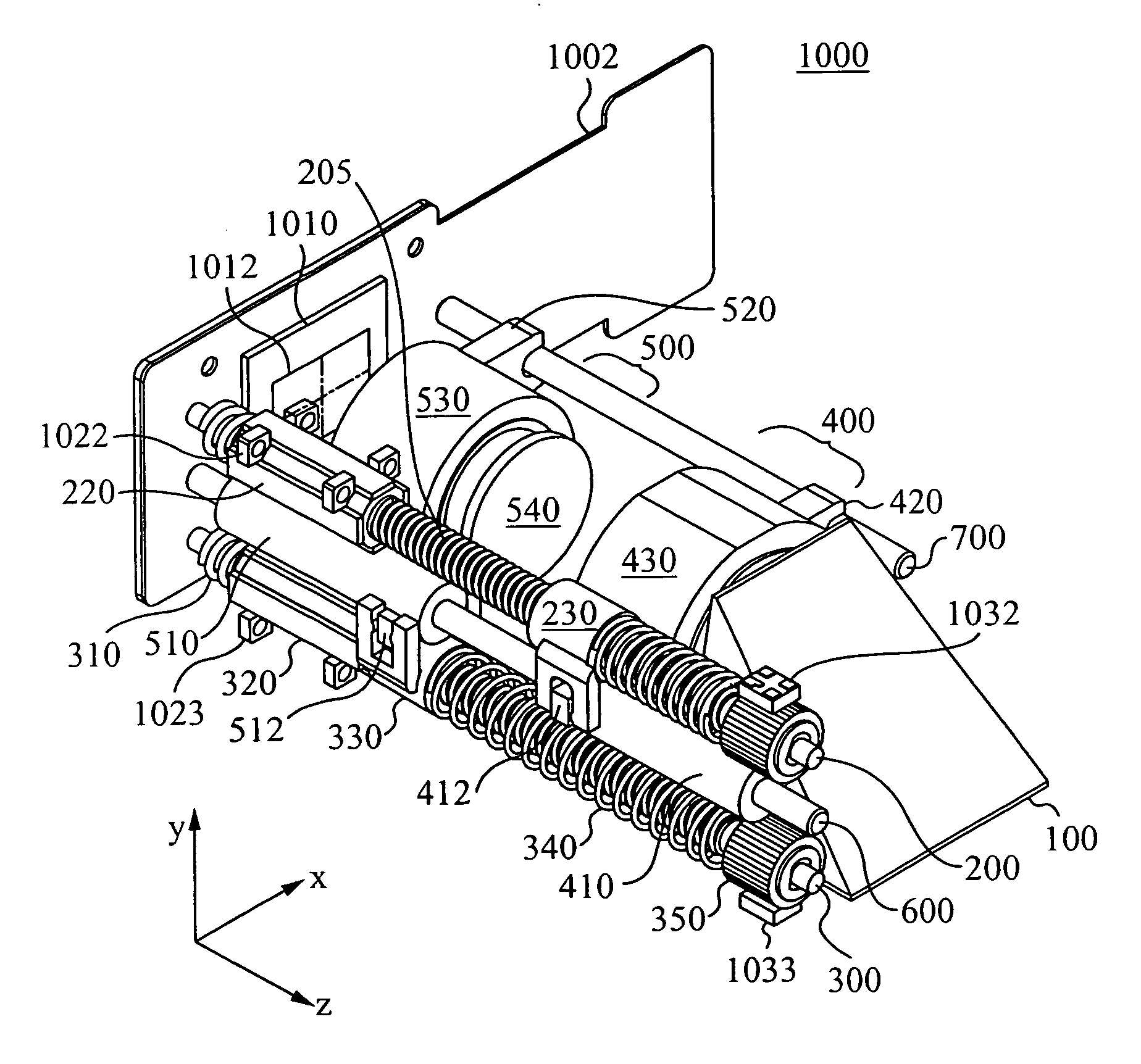
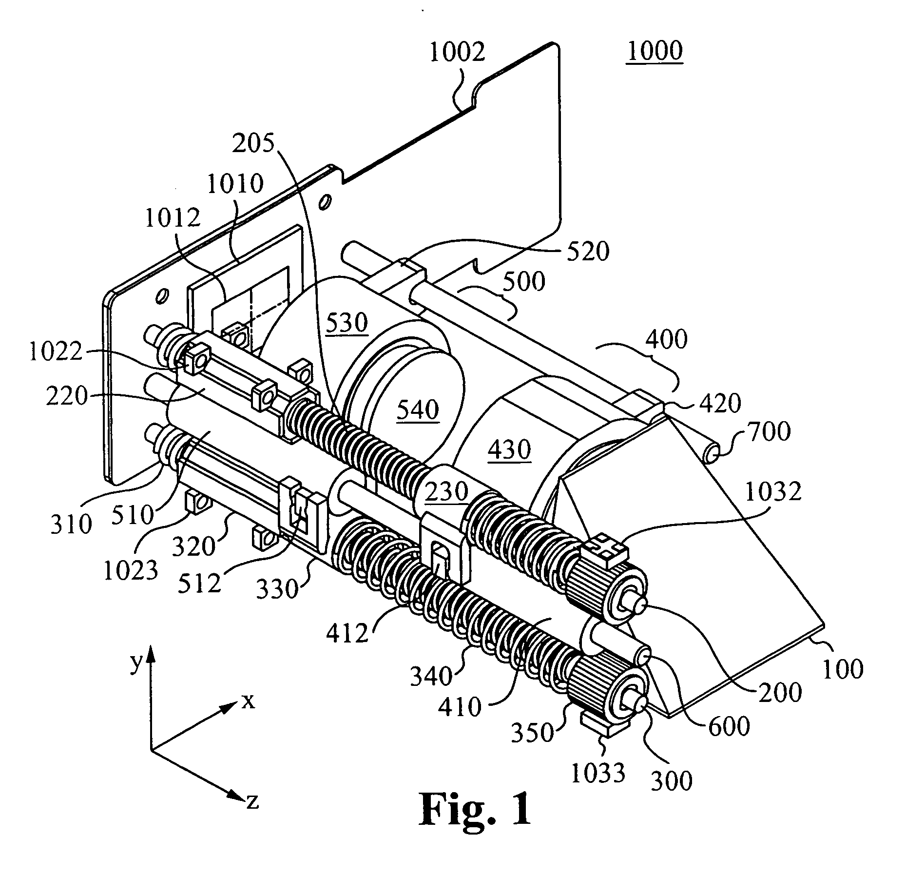
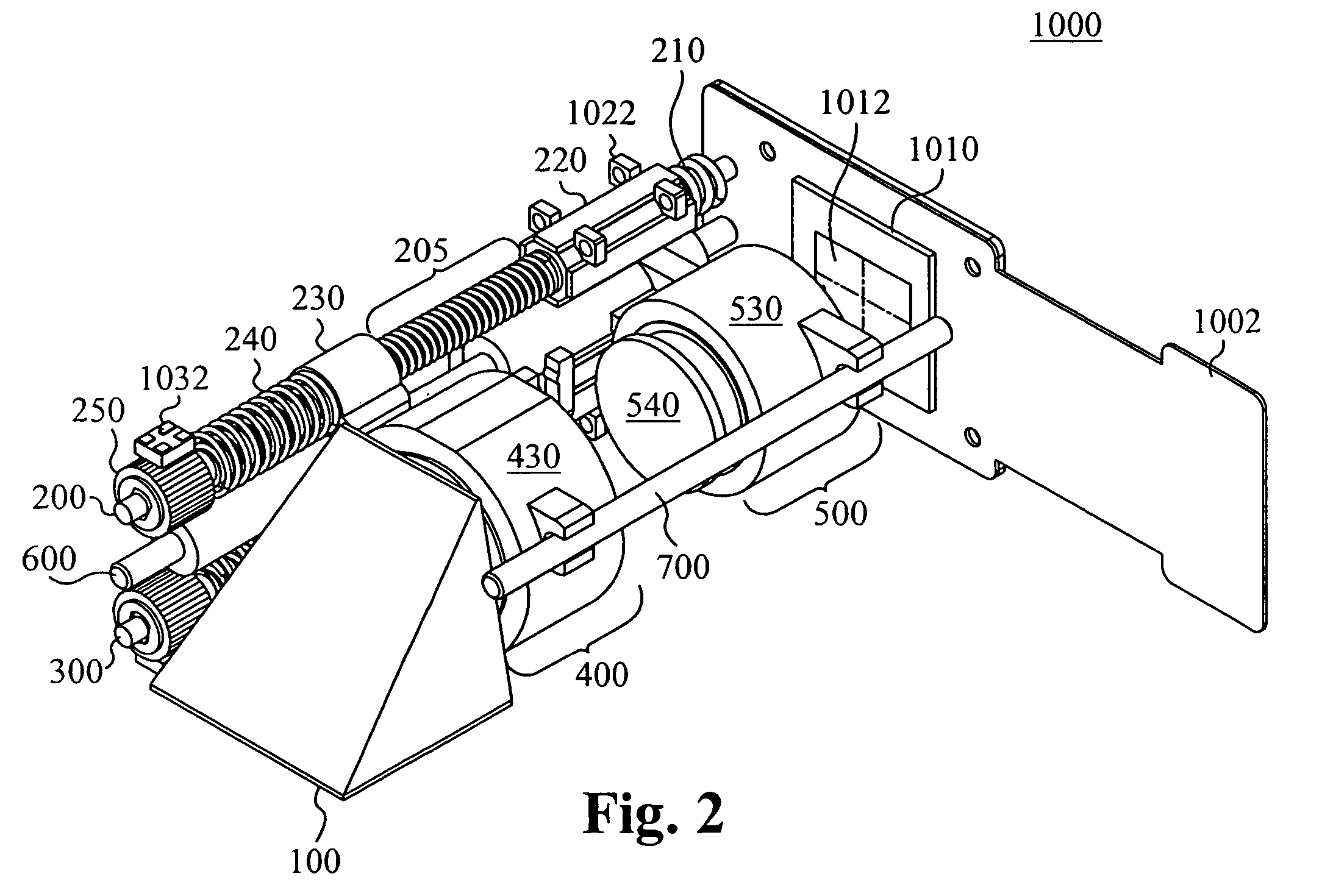
[0044]FIG. 1 illustrates an auto-focus and zoom module 1000 in accordance with some embodiments of the invention. As shown in this figure, the module 1000 includes a front optics group 400, a rear optics group 500, and an image sensor 1010. The front optics group 400 and rear optics group 500 typically comprise one or more optical elements such as a lens. For instance, the module 1000 illustrated in FIG. 4 includes several optical lenses in both the front optics group 400 and rear optics group 500. However, one of ordinary skill will recognize both more com...


PUM


Abstract

An optical module includes a first optics group, a second optics group, and an image sensor, wherein the first optics group and second optics group are configured to provide an image having a focus and a magnification to the image sensor. In some embodiments of the present invention, a first optics assembly includes a first optics group coupled to a threaded portion of a first lead screw so that rotation of the first lead screw results in translation of the first optics group along an axis of the first lead screw, a first actuator for rotating the first lead screw; and a first sensing target configured to permit detection of rotation of the first lead screw. In some embodiments of the present invention a second optics assembly includes a second optics group coupled to a threaded portion of a second lead screw so that rotation of the second lead screw results in translation of the second optics group along an axis of the second lead screw, a second actuator for rotating the second lead screw, and second means for sensing configured to detect rotation of the second lead screw.

Description

RELATED APPLICATIONS [0001] This Patent Application claims priority under 35 U.S.C. 119(e) of the co-pending U.S. Provisional Pat. App. No. 60 / 715,533, filed Sep. 8, 2005, entitled “3× ZOOM MINI MODULE”, which is hereby incorporated by reference.FIELD OF THE INVENTION [0002] The disclosure relates to camera optics, specifically an auto-focus and zoom module. BACKGROUND [0003] Recently, there have been numerous developments in digital camera technology. One such development is the further miniaturization of optical and mechanical parts to the millimeter and sub millimeter dimensions. The shrinkage in the moving parts of cameras has allowed the implementation of modern digital camera and optical technology into a broader range of devices. These devices are also constantly being designed and constructed into smaller and smaller form factor embodiments. For example, commercially available personal electronic devices such as cellular phones, personal digital assistants (PDAs), and wrist ...

Claims


Application Information

Patent Timeline
IPC IPC(8): G03B17/00
CPCG01D5/3473G02B7/102G03B13/36Y10T74/19898H04N5/2254H04N5/23212G03B17/02H04N23/55G02B7/08G02B7/282G03B3/10H04N23/50
Inventor WESTERWECK, LOTHARGRZIWA, WOLFRAMMOORE, RUSSEL L.
Owner NANCHANG O FILM OPTICAL ELECTRONICS TECH CO LTD
Learn More