Eureka AIR delivers breakthrough ideas for toughest innovation challenges, trusted by R&D personnel around the world.

LED illuminator with retro reflector

a technology of led illuminator and retro reflector, which is applied in the field of whitelight optical system, can solve the problems of poor intensity, combination of poor cri, poor cct, poor intensity, etc., and achieve the effects of high intensity, reduced package size, and high intensity

Inactive Publication Date: 2007-03-08
INNOVATIONS & OPTICS
View PDF22 Cites 49 Cited by
  • Summary
  • Abstract
  • Description
  • Claims
  • Application Information

AI Technical Summary

Benefits of technology

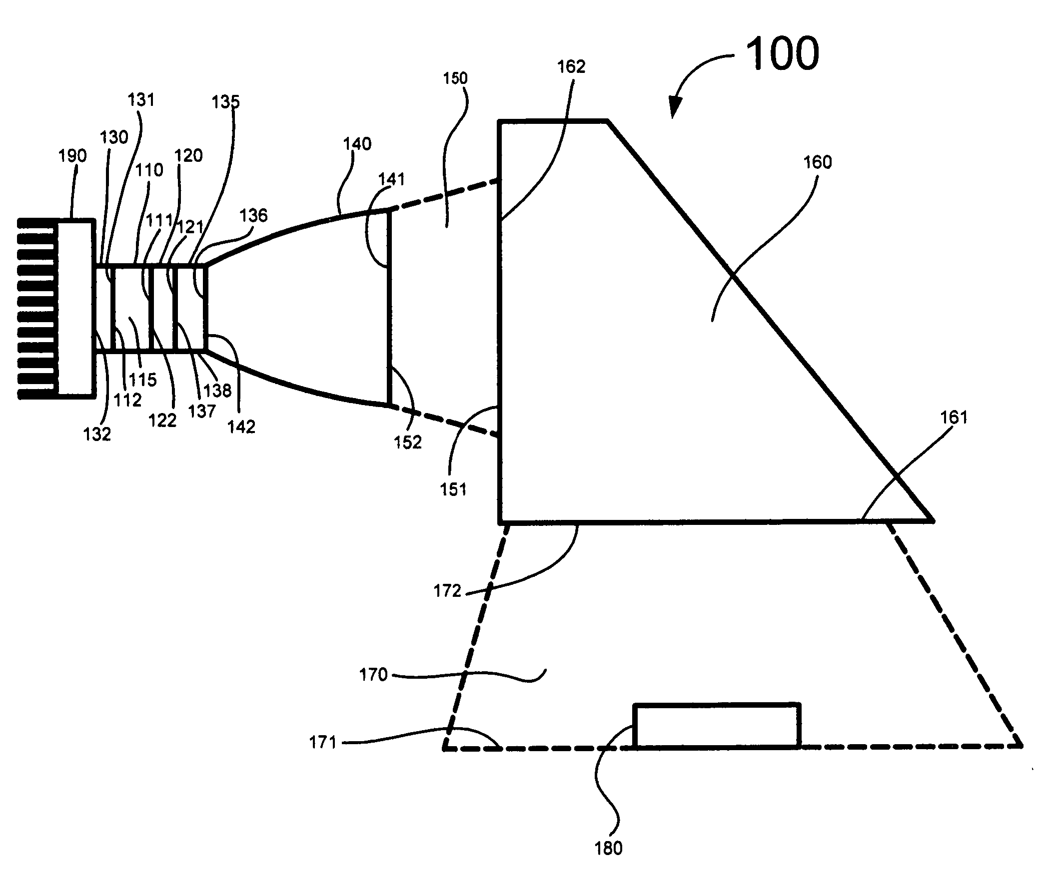
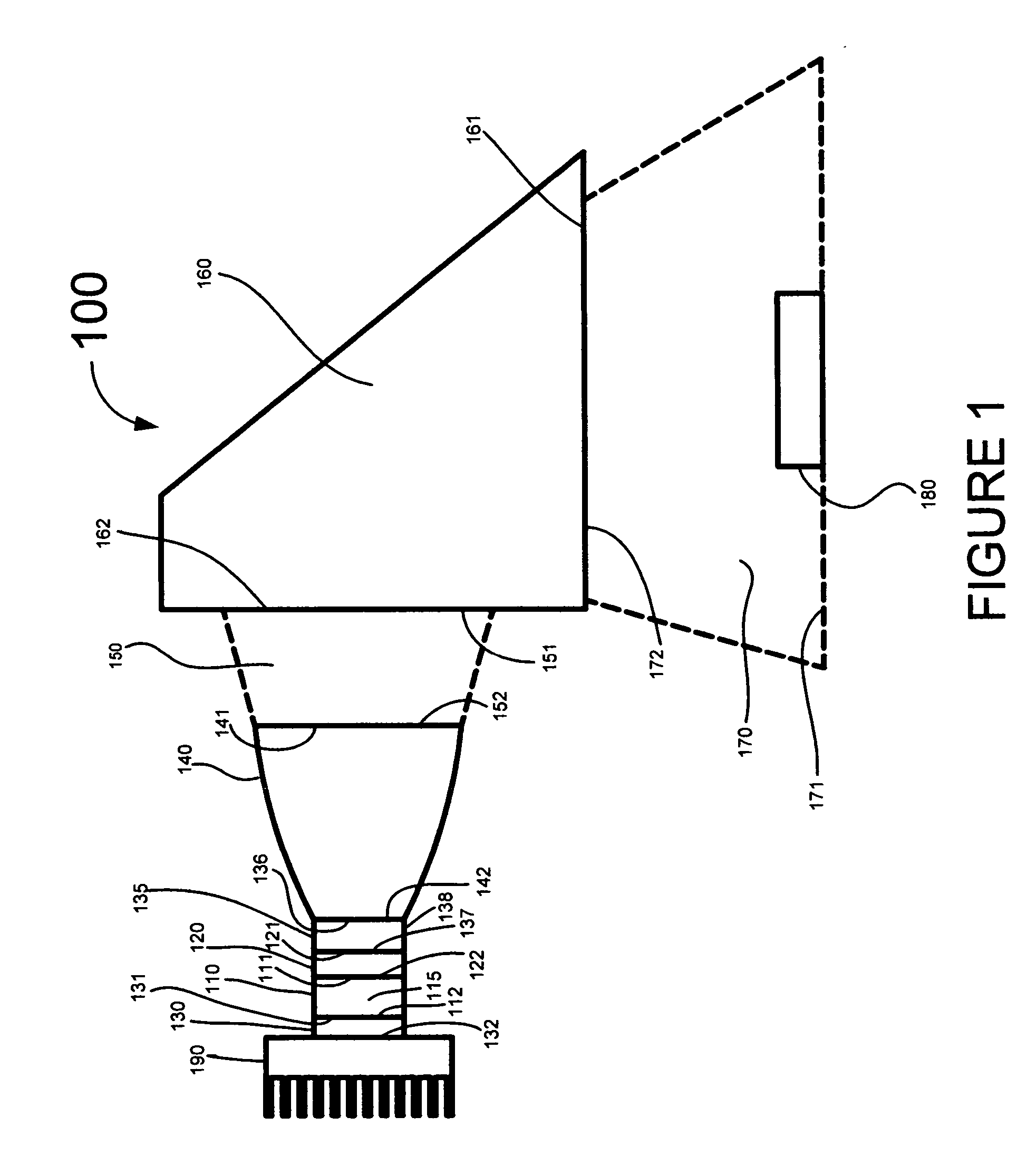
[0011] A preferred embodiment of the invention provides a LED lighting device that produces high intensity, spatially uniform, white light in the near and far fields in a reduced package size that does not significantly heat the surrounding environment, wherein the white light is produced by using a phosphor layer in conjunction with a single LED.
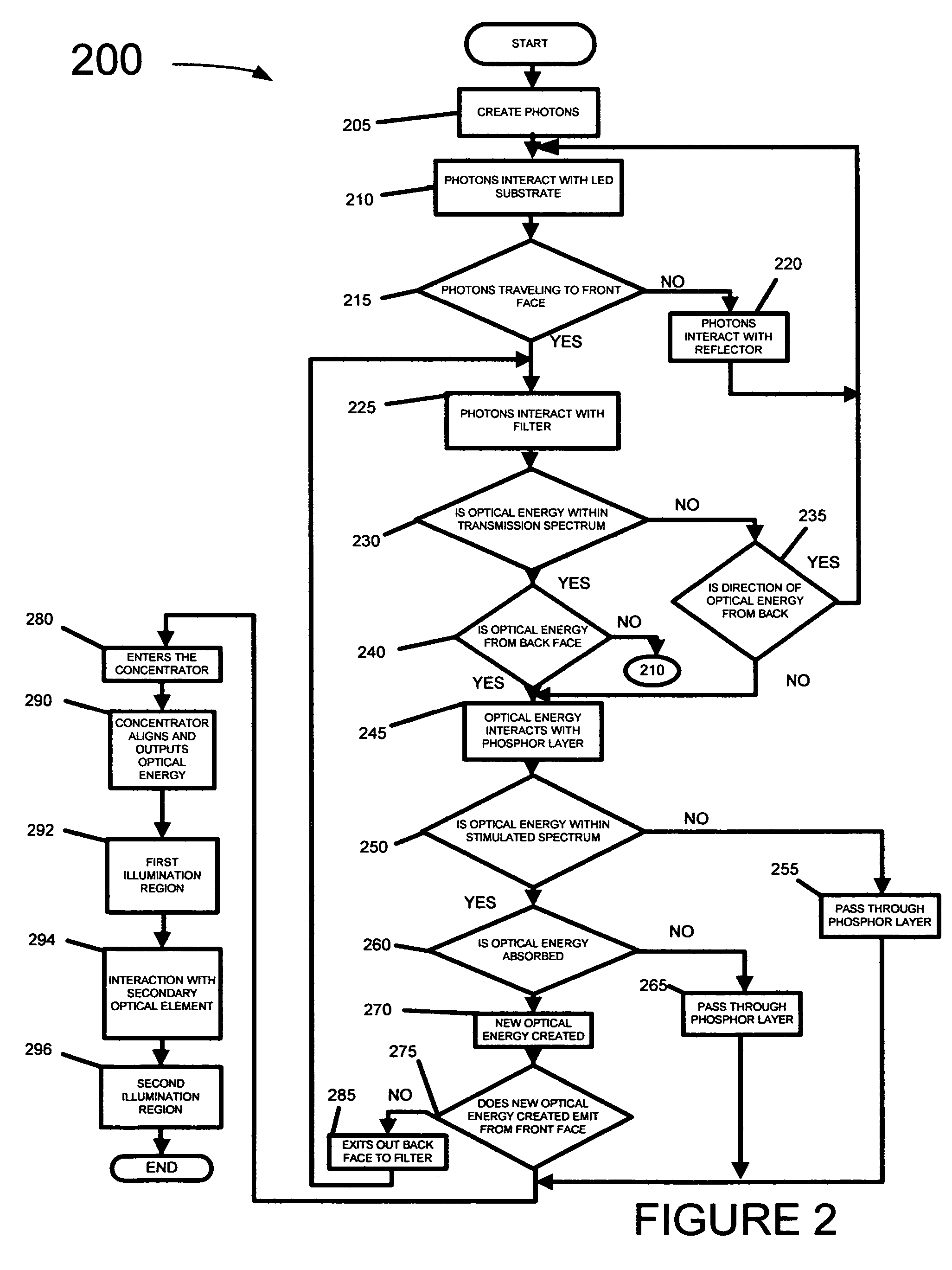
[0012] An alternative embodiment of the invention provides a method for obtaining high intensity, spatially uniform, white light in the near and far fields in a reduced package size that does not significantly heat the surrounding environment, wherein the white light is produced by using a phosphor layer in conjunction with a single LED.
[0013] A preferred embodiment of the invention provides an LED curing device that produces high intensity, spatially uniform, optical energy for curing in the near and far fields in a reduced package size that does not significantly heat the surrounding environment, wherein the optical energy is produced by using single and multiple LED's.

Problems solved by technology

Traditional light sources, however, suffer from, for example, but not limited to, combinations of a poor CRI, poor CCT, poor intensity, short usage life, large power electrical consumption, large package size, thermal energy, and / or are electrically and; or optically inefficient.
In addition. tungsten filament lamps have a low electrical to optical efficiency and, thus, require large amounts of electrical power to generate high intensity optical energy, which results in large quantities of thermal energy.
Furthermore. high power tungsten lamps have a low lamp lifetime, usually operating for about 500 hours.
Tungsten -halogen lamps, when used in conjunction with filters, produce a CCT of above 4000K but still suffer from many of the same disadvantages of Tungsten filament lamps.
The optical energy below the white light CCT range is referred to as ultra violet light and in many circumstances an unwanted or damaging byproduct.
Xenon arc lamps provide optical energy with higher intensity than metal halide lamps. but have a low luminous efficiency and low lamp life time (around 500 hours).
Furthermore, traditional light sources such as arc lamps, for example, when used as a light source for a less than spherical illumination region, are optically inefficient.
The full spherical discharge of optical energy is difficult to capture into a particular illumination region.
However, commercially available LED's that emit white light have low CCT and have poor control.
In addition, LED's provide insufficient optical energy for most illumination applications.

Method used


Image

  • LED illuminator with retro reflector
  • LED illuminator with retro reflector
  • LED illuminator with retro reflector

Examples


example

[0128] Referring to FIG. 1, in a preferred embodiment of the invention, the LED optical source 110 is a combination of two LED optical sources. The first LED optical source 110 is an array of eight CREE Xbright Power Chip LED C470-XB900, which requires 1,125 milliwatts of electric power (i.e., 350 milliamps at 3.5 volts) to produce 150 milliwatts of optical power from each LED for optical energy with a spectral width of 440 nanometers to 480 nanometers and a spectral peak at 460 nanometers. The total optical power for the first LED optical source is therefore 1,350 milliwatts. The first LED optical source represents the stimulated optical energy. The second LED optical source 110 is one Lumileds HWFR-B515, which requires 700 milliwatts of electric power (i.e. 250 milliamps at 2.8 volts) to produce 150 milliwatts of optical power from the LED for optical energy with a spectral width of 620 nanometers to 660 nanometers and a spectral peak at 640 nanometers. The second LED optical sour...


PUM


Abstract

An illuminator with blue and red LEDs, a reflector upstream of the LEDs for capturing upstream light emitted out of the back surfaces of the LEDs and redirecting downstream as useful illumination, a band pass filter for conditioning the downstream light, a phosphor layer for changing the spectral properties of light from the LEDs, and a non-imaging concentrator for creating a beam of illumination over a predetermined solid angle, uniformity, and spectral content.

Description

CROSS-REFERENCE TO RELATED APPLICATIONS [0001] This application is a divisional of U.S. patent application Ser. No. 10 / 334,525 filed on Dec. 30, 2002 bearing the title, LED WHITE LIGHT OPTICAL SYSTEM, the entire contents of which is incorporated herein by reference.FIELD OF THE INVENTION [0002] This invention relates to a white-light optical system, and more particularly, to a LED white-light optical system that provides spatially uniform high intensity white light over a near field diverging region in a highly efficient manner. BACKGROUND OF THE INVENTION [0003] Many optical energy applications require high intensity, spatially uniform, white light that does not significantly heat the surrounding environment in the near field and / or far field. More specifically, many applications require correlated color temperatures between 4100-4900K (i.e., white light) with a color rendering index (“CRI”) between 90 to 100. [0004] Correlated color temperature (“CCT”) is a numerical assignment of...

Claims


Application Information

Patent Timeline
Patent Type & Authority Applications(United States)
IPC IPC(8): F21V9/00A61N5/06H01L33/50
CPCA61N2005/0652A61N5/062
Inventor BRUKILACCHIO, THOMAS J.
Owner INNOVATIONS & OPTICS
Why Eureka
Eureka Blog
Learn More