
Lighting assembly for a luminescence analysis apparatus, in particular a fluorescence mrcroscope, and luminescence analysis apparatus equipped with such a lighting assembly

a technology for luminescence analysis and lighting assembly, which is applied in the field of fluorescence mrcroscopes and luminescence analysis apparatuses equipped with such, can solve the problems of complex electronics, large energy consumption, and high cost of conventional discharge or halogen lamps, and achieves the effects of less energy, high efficiency and compact structur

Inactive Publication Date: 2007-03-08
FRAEN CORPORATION
View PDF9 Cites 12 Cited by
  • Summary
  • Abstract
  • Description
  • Claims
  • Application Information

AI Technical Summary

Benefits of technology

[0010] In particular, it is an object of the invention to provide a fluorescence microscope, and a luminescence analysis apparatus in general, which is compact (at least portable), and which is cheap and easy to produce and use.
[0013] The apparatus equipped with the lighting assembly according to the invention eliminates the aforementioned drawbacks of the known art by being, in particular, highly compact and cheap to produce. Moreover, LEDs consume much less energy, are more efficient, and have a much longer life (typically over 50000 hours, as compared with the 100-1000 hours of conventional lamps) than sources normally used in luminescence analysis equipment.

Problems solved by technology

In particular, conventional discharge or halogen lamps are relatively expensive, consume a large amount of energy, and are of short life.
Moreover, discharge and halogen lamps call for complex electronics for controlling turn-on and discharge, and relatively complex, i.e. high-cost, optical systems for concentrating emission on the small area of interest.
Finally, lamps of this sort, and therefore the microscope as a whole, are normally fairly bulky, so that portable, or at least small-size, apparatuses are impossible to achieve.
This problem is further compounded by the high energy consumption of the lamps, which cannot be battery-powered.
Fluorescence microscopes equipped with laser sources also have some of these drawbacks, on account of laser sources in particular being fairly complex, expensive and bulky.
Similar drawbacks are also found in other types of fluorescence and luminescence analysis equipment in general, as used for example in spectrophotometry, fluorometry, etc.
In other words, compact (portable), low-cost, low-power fluorescence microscopes or luminescence analysis equipment in general are not currently available.

Method used


Image

  • Lighting assembly for a luminescence analysis apparatus, in particular a fluorescence mrcroscope, and luminescence analysis apparatus equipped with such a lighting assembly
  • Lighting assembly for a luminescence analysis apparatus, in particular a fluorescence mrcroscope, and luminescence analysis apparatus equipped with such a lighting assembly
  • Lighting assembly for a luminescence analysis apparatus, in particular a fluorescence mrcroscope, and luminescence analysis apparatus equipped with such a lighting assembly

Examples


Embodiment Construction

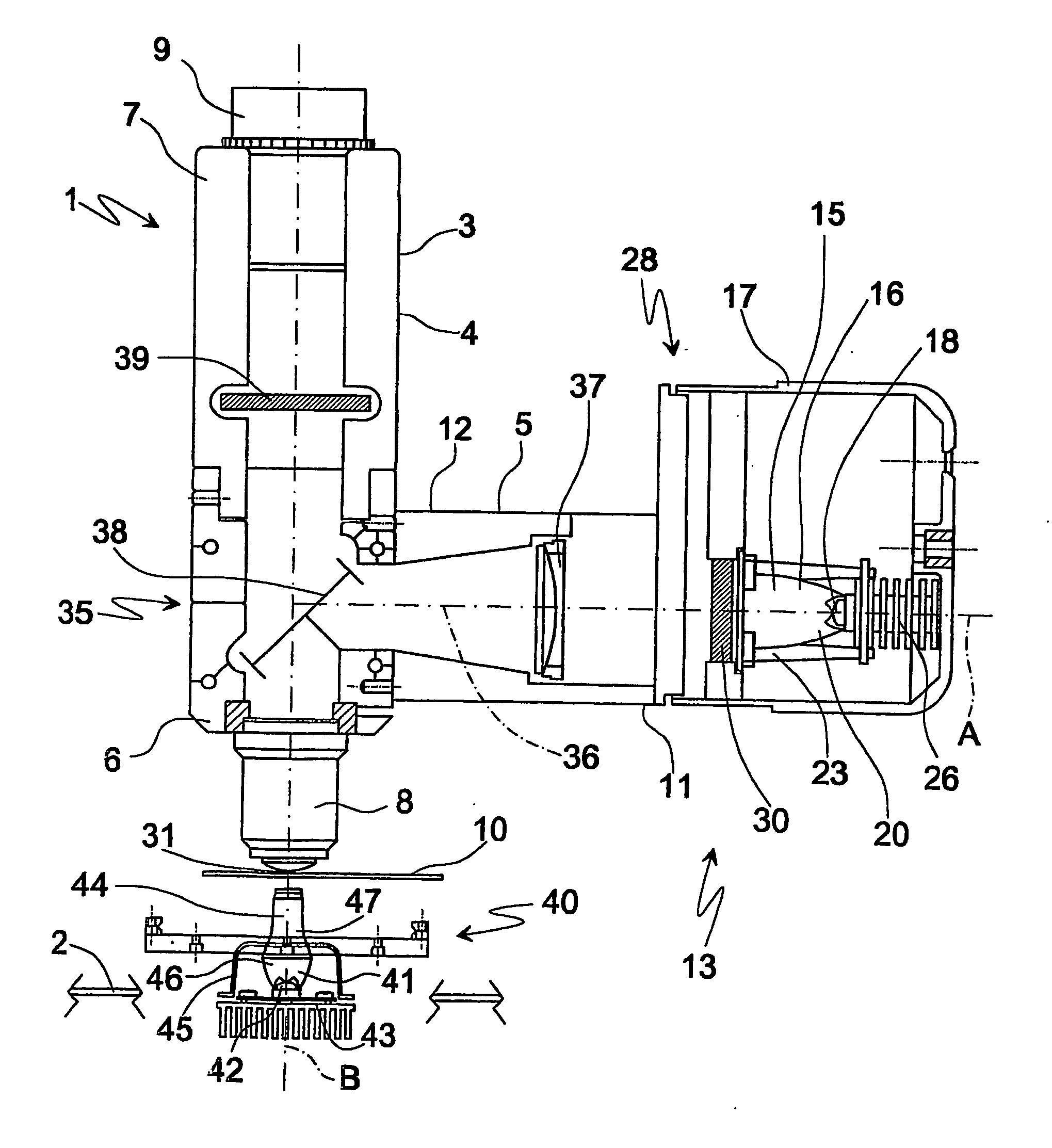
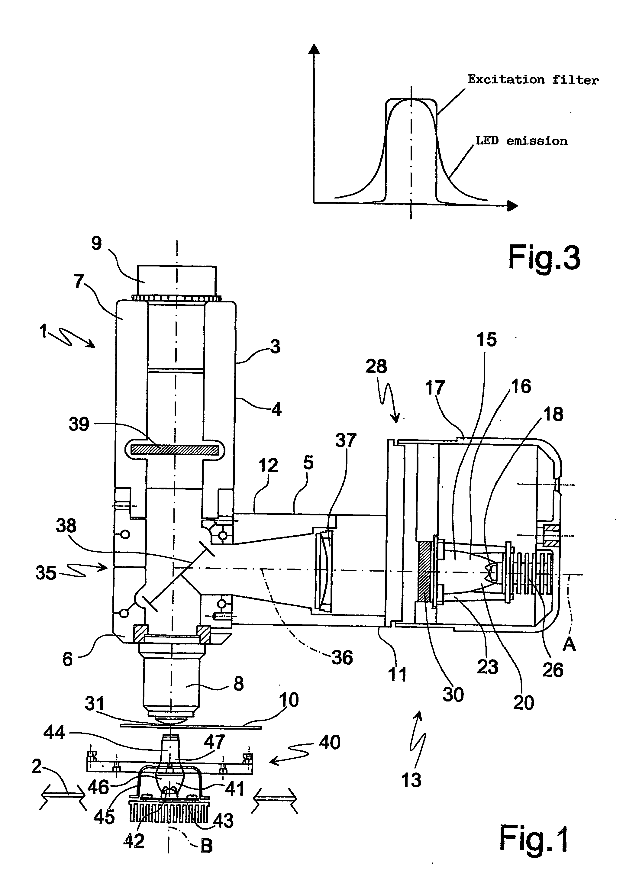
[0021] Number 1 in FIG. 1 indicates as a whole a luminescence analysis apparatus. In the example shown, apparatus 1 is an apparatus for fluorescence microscopy, i.e. an incident-light fluorescence microscope hereinafter referred to, for the sake of simplicity, as microscope 1.

[0022] Microscope 1 comprises a base structure 2, shown only schematically in FIG. 1, which in turn comprises casing 3 having a tubular main body 4, from which projects a tubular lateral body 5. Two axially opposite ends 6, 7 of main body 4 are fitted respectively with an objective 8 and an eyepiece 9, both of which are substantially known; and a known sample support 10 is located opposite objective 8.

[0023] A free end 11 of lateral body 5, opposite an end 12 attached to main body 4, is fitted with a lighting assembly 13, which comprises a lighting unit 15 having a preassembled module 16 housed inside a housing 17.

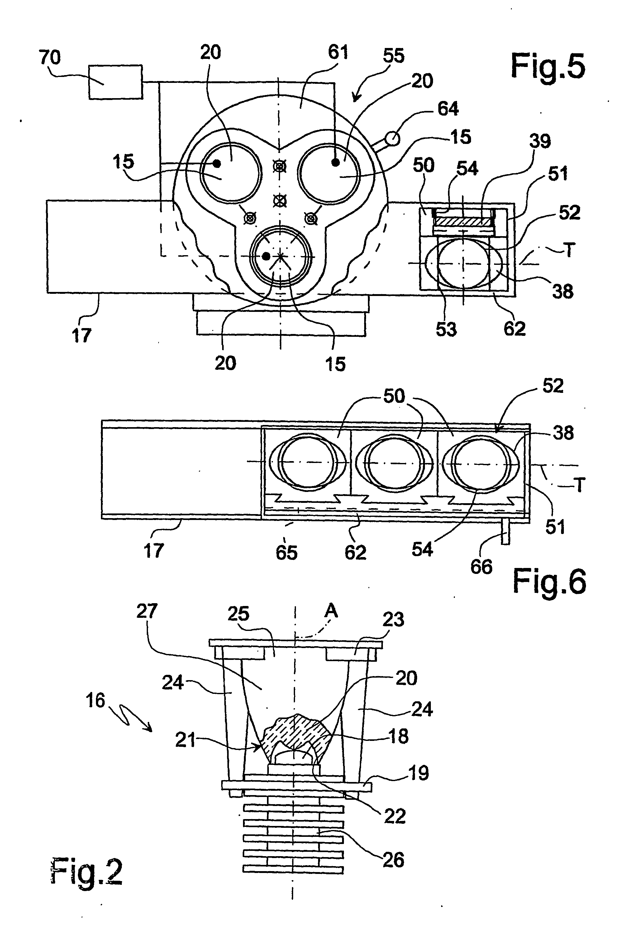
[0024] As shown in more detail in FIG. 2, module 16 comprises a LED (light-emitting diode or si...


PUM


Abstract

A luminescence analysis apparatus, in particular for fluorescence microscopy, has a lighting assembly having a lighting unit which includes a preassembled module housed inside a housing; the module is defined by a LED mounted on a plate, and by an optical collimating element connected integrally to the LED and located in close proximity to the LED; the optical element is a catadioptric collimator made of transparent plastic material and designed to internally convey and transmit the light emitted by the LED, so as to generate a substantially parallel beam of light rays which is directed onto a luminesce sample for analysis.

Description

TECHNICAL FIELD [0001] The present invention relates to a lighting assembly for a luminescence analysis apparatus, in particular a fluorescence microscope, and to a luminescence analysis apparatus, in particular for fluorescence microscopy, comprising such a lighting assembly. BACKGROUND ART [0002] As is known, in fluorescence microscopy, the sample contains a fluorescent substance (contained naturally in or introduced into the sample) which, when struck and excited by a light beam in a given spectral band, itself fluoresces in a different (higher-wavelength) spectral band. Emission by the sample is then collected by a special device and observed directly in an eyepiece. [0003] As fluorescence analysis normally calls for intense illumination of the sample, concentrated in a small area, known fluorescence microscopes employ high-efficiency light sources, typically short-arc discharge or halogen lamps or laser sources. [0004] Microscopes equipped with light sources of this type, howev...

Claims


Application Information

Patent Timeline
IPC IPC(8): G02B21/06G02B21/16
CPCG02B21/16G02B21/06
Inventor ANGELINI, MARCOBARALDO, NATALEBIGLIATI, CLAUDIASCODES, LUCA
Owner FRAEN CORPORATION
Learn More