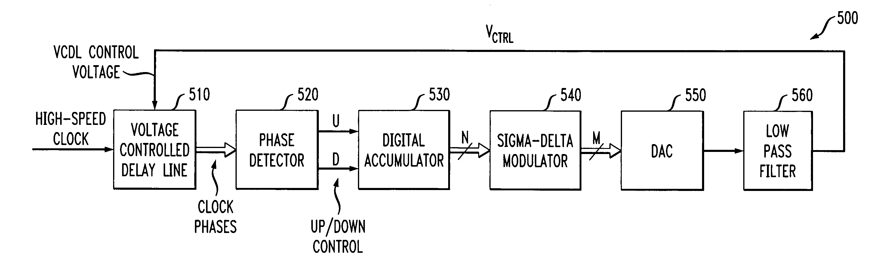
Method and apparatus for sigma-delta delay control in a Delay-Locked-Loop
a delay control and delta technology, applied in the direction of automatic control, electrical equipment, etc., can solve the problems of affecting the size of the integrated circuit incorporating such a dll, affecting the linearity of the integrated circuit, and affecting the size of the integrated circui
- Summary
- Abstract
- Description
- Claims
- Application Information
AI Technical Summary
Benefits of technology
Problems solved by technology
Method used
Image


Examples
Embodiment Construction
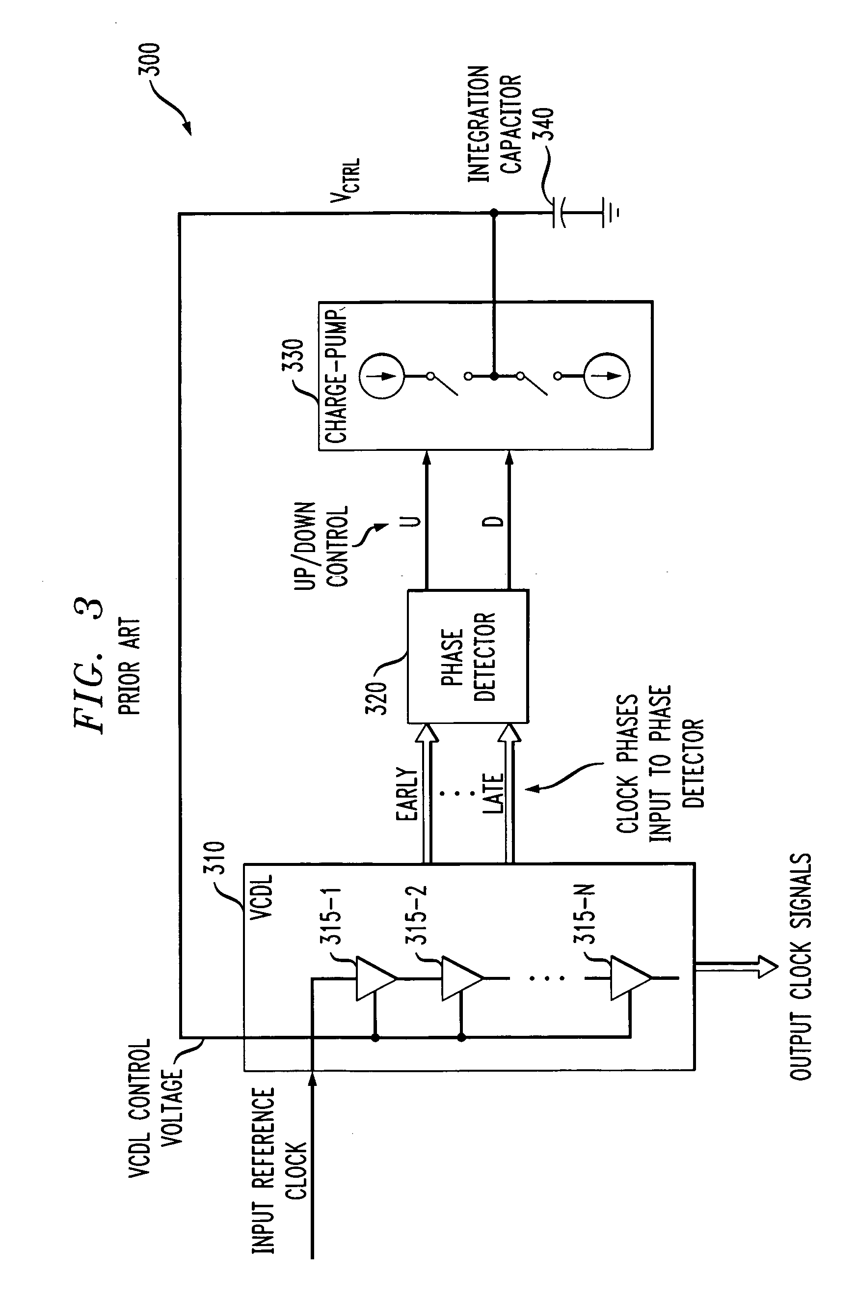
[0022]FIG. 3 illustrates a conventional DLL circuit 300. As shown in FIG. 3, the DLL circuit 300 comprises a voltage controlled delay line (VCDL) 310, a phase detector 320, a charge pump 330, and an integration capacitor 340. The voltage controlled delay line 310 can be embodied, for example, using the VCDL circuits described in U.S. patent application Ser. No. 10 / 999,900, filed Nov. 30, 2004, entitled, “Voltage Controlled Delay Loop and Method with Injection Point Control,” incorporated by reference herein.
[0023] As shown in the exemplary embodiment of FIG. 3, a voltage controlled delay line 310 is typically comprised of a cascaded chain of delay elements 315-1 through 315-N, hereinafter, collectively referred to as delay elements 315, each having a nominal delay value that is controlled by the integration capacitor voltage, VCTRL, to produce a plurality of phase shifted clock signals, such as the “early” and “late” clock signals shown in FIG. 3, as well as a plurality of addition...
PUM
 Abstract
Description
Claims
Application Information
 - R&D
- Intellectual Property
- Life Sciences
- Materials
- Tech Scout
- Unparalleled Data Quality
- Higher Quality Content
- 60% Fewer Hallucinations
Browse by: Latest US Patents, China's latest patents, Technical Efficacy Thesaurus, Application Domain, Technology Topic, Popular Technical Reports.
© 2025 PatSnap. All rights reserved.Legal|Privacy policy|Modern Slavery Act Transparency Statement|Sitemap|About US| Contact US: help@patsnap.com