
Scalable microbial fuel cell with fluidic and stacking capabilities

a fuel cell and microbial technology, applied in the field of fuel cells, can solve the problems of limited proton conductance or throughput, particularly flawed solar power assumption, and inability to optimize macroscopic devices in terms of proton transport from the anode chamber

Inactive Publication Date: 2007-03-01
UNITED STATES OF AMERICA
View PDF13 Cites 78 Cited by
  • Summary
  • Abstract
  • Description
  • Claims
  • Application Information

AI Technical Summary

Problems solved by technology

This assumption is particularly flawed for solar power due to dramatic drops in power density, depending upon several uncontrollable environmental conditions.
These macroscopic devices may not be optimized in terms of proton transport from the anode chamber to the cathode chamber.
This design limits proton conductance, or throughput, and lowers the efficiency of the device.
The macroscopic scale of the chambers is not designed for efficiency, that is to say, a majority of bacteria present in the chamber do not contribute their electrons to the anode due to their large average distance from the anode.
In addition, attempts are not made in these designs to flow fluid through the chambers, resulting in potential mass transfer limits on power production.
However, these demonstrations have been limited to the seafloor and riverbeds in order to maintain an anoxic environment for the anode (sub-sediment).
In addition, the prospect of boosting output power by using hydrogen is impossible in an aerobic environment because hydrogen is evolved only under anaerobic culture conditions.
However, there are drawbacks to Lin's device.
These electrodes have relatively small surface areas (0.5 cm2) and cannot be enhanced without making the device footprint larger.
Secondly, Lin's device is not scalable, limiting it to micro-scale power generation and severely limited power regimes.
Each of these limitations reduces the usefulness of this invention, because there may be no applications suitable for the amounts of power potentially generated by such a device.
Without novel designs or scientific breakthroughs, the energy output of a miniaturized device would be limited to nW's or less due to the current 2D micro-fabricated design, resulting in smaller electrode surface area and the inability to efficiently stack and wire the cells together.

Method used


Image

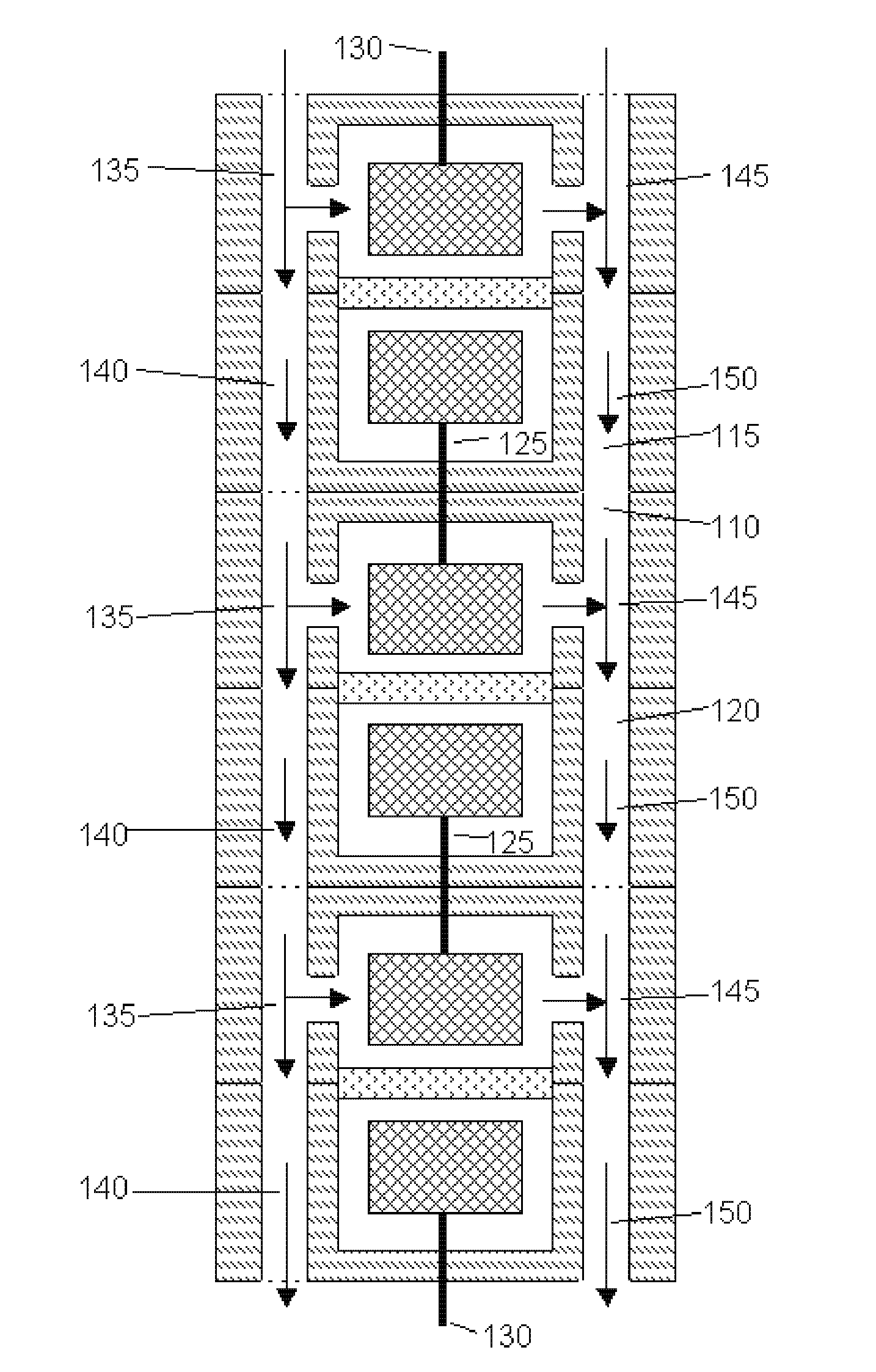
  • Scalable microbial fuel cell with fluidic and stacking capabilities
  • Scalable microbial fuel cell with fluidic and stacking capabilities
  • Scalable microbial fuel cell with fluidic and stacking capabilities

Examples


example

[0054] Bacterial Culture Conditions-The facultative anaerobe S. oneidensis strain DSP10 was used for all experiments. Luria-Bertani (LB) broth (Difco Laboratories, Detroit, Mich.) was inoculated with DSP10 and incubated at room temperature for 5 days with shaking at 100 rpm. After assembling the mini-MFC (described below), 20-60 mL DSP10 culture was transferred to a sterile 100 mL Erlenmeyer flask, which was then capped with a sterile rubber stopper fitted with a cotton-plugged tube open to air and two glass tubes attached to influent and effluent lines. Within 1 hr, dissolved oxygen measurements (ISO2 probe, WPI, Inc., Tampa, Fla.) for both influent and effluent lines showed that the DSP10 culture had scavenged all available dissolved O2 (0.1±0.2 ppm). Sodium lactate as substrate was added every 1-3 days. Some bacterial cultures had the soluble electron mediator anthraquinone-2,6-disulfonate (AQDS; 100 μM) added to the anolyte.

[0055] Mini-MFCassemblyand operation-The mini-MFC desi...


PUM


Abstract

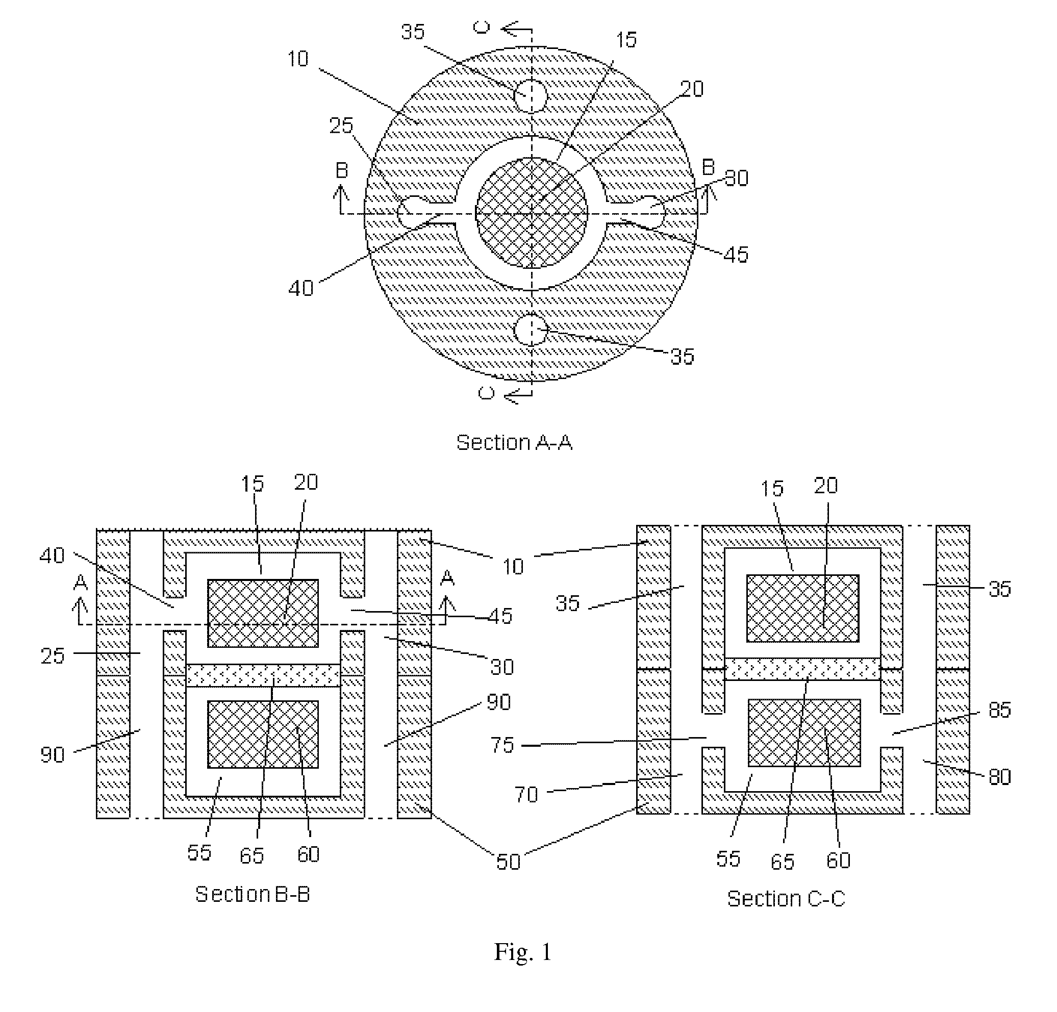
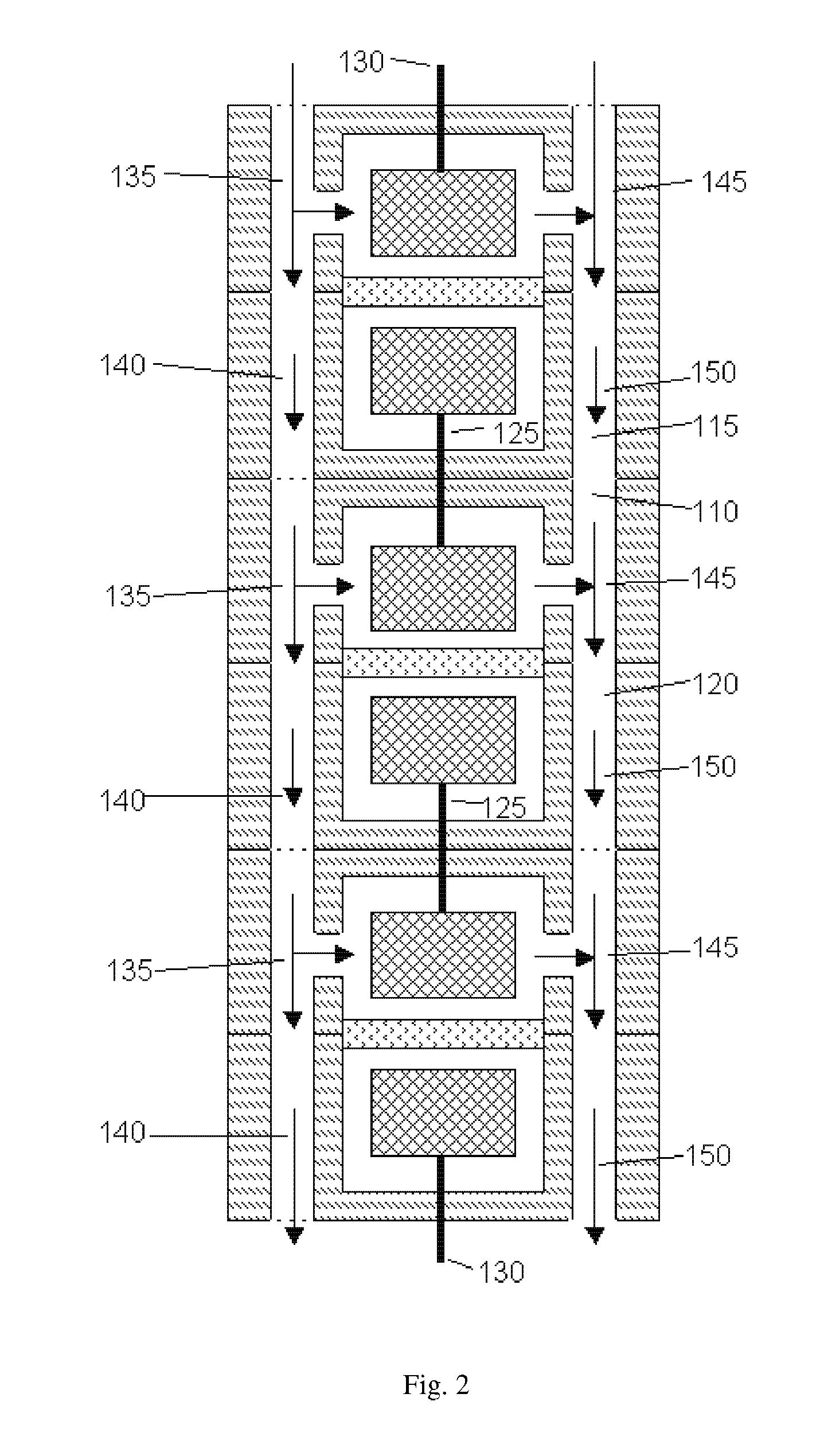
A fuel cell having: a proton exchange membrane; anode and cathode housings containing chambers; a three-dimensional anode and cathode. Each housing may have a feed passage, a waste passage, and two through passages. The anode feed passage and the anode waste passage are each coupled to the anode chamber and to one of the cathode through passages and vice versa. The anode chamber may have bacteria capable of donating electrons to the anode upon exposure to a fuel. Solutions may be circulated through the passages and chambers.

Description

CROSS REFERENCE TO RELATED APPLICATIONS [0001] This application claims the benefit of U.S. Provisional Patent Application No. 60 / 712,611, filed on Aug. 30, 2005 incorporated herein by reference.FIELD OF THE INVENTION [0002] The invention is generally related to fuel cells. DESCRIPTION OF RELATED ART [0003] Microbial fuel cells (MFCs) offer a clean, renewable, and potentially autonomous source of energy that could be an alternative to environmental power sources such as solar, geothermal, and wind. They rely upon the metabolic cycle of living bacteria to generate electrons that are then harvested by the anode and transferred to the cathode where a complementing reduction reaction occurs. [0004] Due to their ability to function in many environments with versatile fuels, microbial fuel cells (MFCs) are a promising power source for applications under extreme or highly variable conditions where other power sources might fail (anaerobic conditions, varying temperature, low / no solar energy...

Claims


Application Information

Patent Timeline
IPC IPC(8): H01M8/02H01M4/86H01M4/96H01M8/16H01M4/90
CPCH01M4/8657H01M8/0232H01M8/0234H01M8/0247H01M8/04097H01M8/1023Y02E60/521H01M8/16H01M8/241H01M8/249H01M2004/8684Y02E60/527H01M8/1039Y02E60/50H01M8/2404
Inventor RINGEISEN, BRADLEYHENDERSON, EMILYWU, PETERPIETRON, JEREMY
Owner UNITED STATES OF AMERICA
Learn More