Method and special device for treating organic wastewater by combination of microbial fuel cell and microalgae culture
A technology for fuel cell and microalgae cultivation, applied in biological water/sewage treatment, chemical instruments and methods, water/sludge/sewage treatment, etc., can solve problems such as energy consumption efficiency, increase transfer rate, and improve removal rate , Improve the effect of wastewater treatment
- Summary
- Abstract
- Description
- Claims
- Application Information
AI Technical Summary
Problems solved by technology
Method used
Image
Examples
Embodiment 1
[0031] Microbial fuel cell and photobioreactor split coupling system structure:
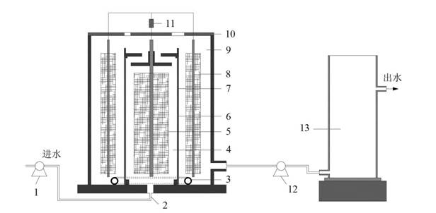
[0032] Microbial fuel cell of the present invention uses anode and cathode chamber continuous flow double-tube structure (see figure 1), mainly including: pump 1, anode chamber water inlet 2, circular aeration tube 3, cylindrical anode chamber 4, anode electrode 5, stainless steel cylinder 6, cation exchange membrane 7, cathode electrode 8, cylindrical cathode chamber 9, cover 10 and resistor 11.
[0033] Microbial fuel cell and photobioreactor split coupling system structure: the cylindrical anode chamber 4 is coaxially arranged in the cylindrical cathode chamber 9, and the cylindrical anode chamber 4 and the cylindrical cathode chamber 9 are exchanged through cation exchange. Membrane 7 separates, cylindrical anode chamber 4 is provided with anode electrode 5, cylindrical cathode chamber 9 is provided with cathode electrode 8, cylindrical cathode chamber 9 designed outside cylindrical anode ch...
Embodiment 2
[0042] The difference from Example 1 is that the microbial fuel cell and photobioreactor are integrated coupling system structure:
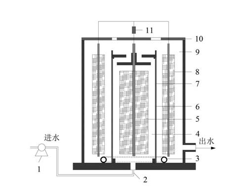
[0043] The cylindrical cathode chamber 9 of the above-mentioned microbial fuel cell is directly used as a photobioreactor, so that the microbial fuel cell and the photobioreactor are integrated (such as Figure 4 shown).
[0044] Sewage is input from the anode chamber water inlet 2 by the pump 1, flows into the photobioreactor (cathode chamber 9) through the top of the cylindrical anode chamber 4, and then passes through the outlet of the bottom side of the cathode chamber 9 as the photobioreactor. Water flows out.
[0045] During the operation of microbial fuel cells, it is usually necessary to blow air in the cathode chamber to provide sufficient oxidants (oxygen) for the cathode reaction, while CO 2 To provide sufficient carbon sources for the growth of microalgae, both require energy consumption, and the utilization efficiency of both gases...
Embodiment 3
[0048] The difference from Example 1 is that the upflow type membraneless microbial fuel cell and photobioreactor are integrated coupling system structure:
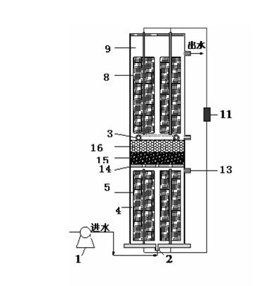
[0049] The anode-cathode compartment continuous flow upflow type microbial fuel cell used in the present invention is mainly processed by organic glass (PMMA) (as Figure 5 shown), mainly includes: pump 1, anode chamber water inlet 2, cylindrical anode chamber 4, anode electrode 5, perforated plexiglass plate 14, glass wool 15, glass bead layer 16, circular aeration tube 3, cathode Electrode 8, cylindrical cathode chamber 9 (photobioreactor), load 11, anode chamber sampling port 13.
[0050] The upflow membraneless microbial fuel cell is formed by sealing one end of a cylindrical PMMA tube with an inner diameter of 8.0 cm and a length of 65 cm. The fuel cell cathode chamber (31 cm high) and anode chamber (24 cm high) are arranged from bottom to top. For the perforated organic glass plate 14, glass wool layer 15 and glass...
PUM
| Property | Measurement | Unit |
|---|---|---|
| diameter | aaaaa | aaaaa |
| clearance rate | aaaaa | aaaaa |
Abstract
Description
Claims
Application Information
 - R&D
- Intellectual Property
- Life Sciences
- Materials
- Tech Scout
- Unparalleled Data Quality
- Higher Quality Content
- 60% Fewer Hallucinations
Browse by: Latest US Patents, China's latest patents, Technical Efficacy Thesaurus, Application Domain, Technology Topic, Popular Technical Reports.
© 2025 PatSnap. All rights reserved.Legal|Privacy policy|Modern Slavery Act Transparency Statement|Sitemap|About US| Contact US: help@patsnap.com


