
Stable state vision inducting brain-machine interface method based on two frequency stimulation of left and right view field

A steady-state visual evoked, brain-computer interface technology, applied in the field of human-computer interaction, can solve the problems of increased selection levels, small selection range of excitation steady-state visual evoked potential frequency, increased user fatigue, etc., and achieves high transmission rate , the effect of simple equipment

Inactive Publication Date: 2009-07-08
TSINGHUA UNIV
View PDF2 Cites 47 Cited by
  • Summary
  • Abstract
  • Description
  • Claims
  • Application Information

AI Technical Summary

Problems solved by technology

In order to make the brain-computer interface system more portable and practical, it is a good way to use a computer screen as a stimulus, but when using a computer screen as a target presentation method, due to the inherent refresh rate problem, the frequency of stimulating the steady-state visual evoked potential The range of options is small, making the number of target presentations limited
For disabled users, fewer objects mean an increased level of choice, which increases user fatigue and complexity of system menus

Method used


Image

  • Stable state vision inducting brain-machine interface method based on two frequency stimulation of left and right view field
  • Stable state vision inducting brain-machine interface method based on two frequency stimulation of left and right view field
  • Stable state vision inducting brain-machine interface method based on two frequency stimulation of left and right view field

Examples


Embodiment Construction

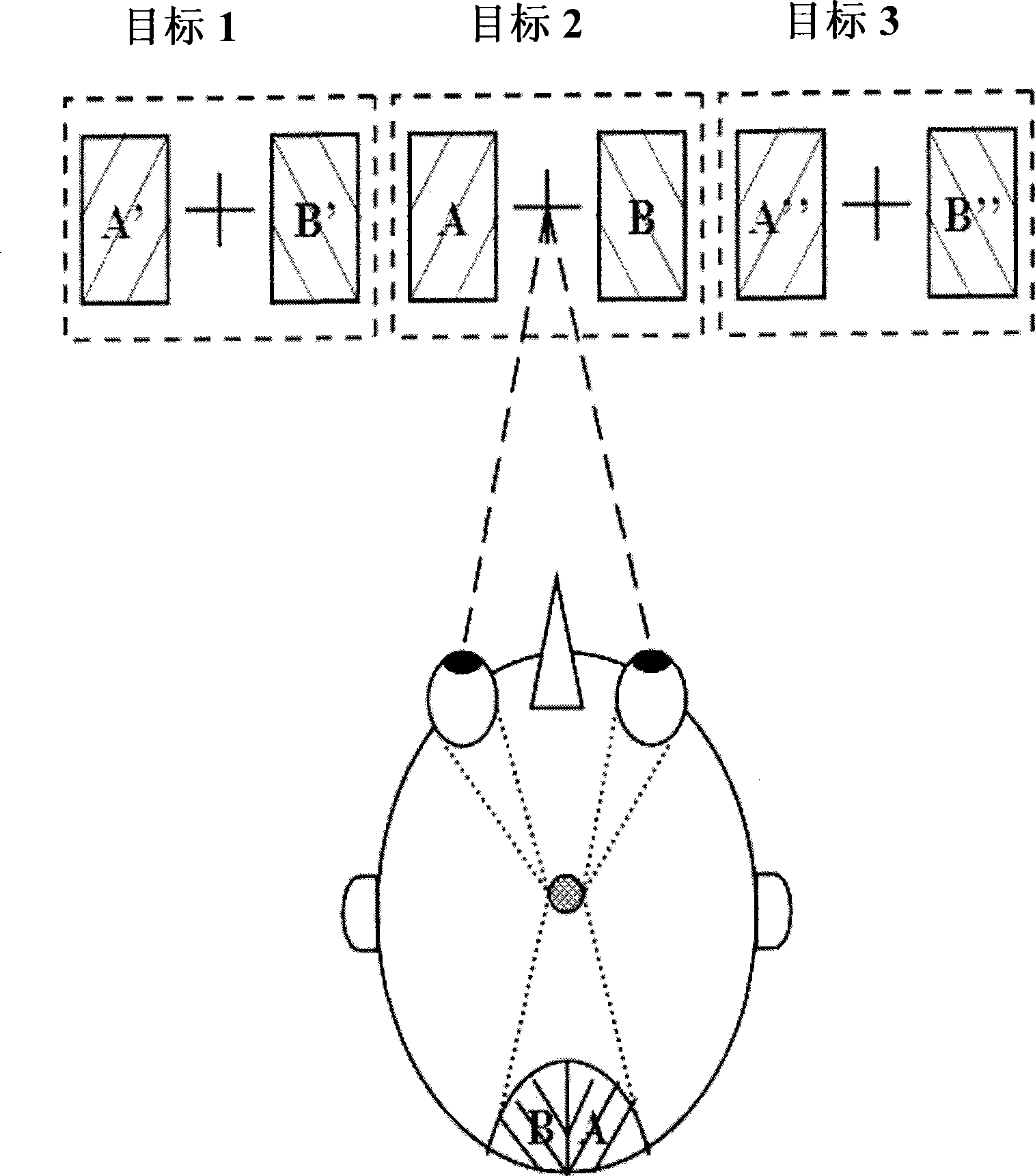
[0026] The stimulation mode invented in this paper can be found in figure 1 shown. The distance between the stimulation blocks on the left and right sides of the cross is 0.5cm, and the size of the stimulation block is 3cm×6cm. The A stimulus block is located in the left visual field of the subject, and the B stimulus block is located in the right visual field. Two stimulus blocks are combined to form a target, and the subjects fixate on the position of the cross, while the conventional steady-state visually evoked BCI uses a frequency flicker block to present the target. According to the principle of visual field intersection in neuroscience, the frequency components of the two visual fields will be projected on the left and right halves of the occipital area of ​​the brain respectively. The letters 'A' and 'B' in the figure indicate the corresponding relationship of projection.

[0027] Here we take the two frequencies of 14 and 18Hz as an example. Combining the two frequ...


PUM


Abstract

A steady-state visual evoked brain-computer interface method is based on the stimulation of two frequencies of left and right visual fields, and relates to a visual evoked presentation method of a visual brain-computer interface. The brain-computer interface method is characterized in that four different targets are combined through two blinking frequencies by utilizing a principle of the crossing of the left and the right visual fields; and a correlational analysis method is used to identify which target is watched by a user after brain electrical acquisition equipment records a multi-brain electrical signal in the visual brain area. The equipment and the method of the invention comprise a recording mode of the brain electrical signal, lead selection and signal preprocessing, and a feature extraction method. The visual target presentation method of the invention can be realized through a screen display of a common computer, and the size, the brightness and even the color of the target can be controlled easily. Compared with other steady-state visual evoked brain-computer interfaces, the presentation method can increase the number of the targets under a condition that the usable frequencies are limited, thereby improving the brain-computer interaction ability.

Description

technical field [0001] The invention belongs to the technical field of human-computer interaction, can help disabled people operate external devices such as computers, and can also be used for new electronic entertainment of brain-computer interaction. Background technique [0002] The brain-computer interface system is a communication system that does not require the participation of peripheral muscles and nerves. It aims to establish a direct communication channel between the human brain and the peripheral world. Or the information is transmitted to the controlled external device, and finally the brain directly controls the external device. EEG signals are usually obtained using non-invasive scalp EEG recordings. [0003] Visual steady-state evoked potential is a signal often used in brain-computer interface BCI. It is the response signal of the visual cortex of the brain to external flickering stimuli greater than 6 Hz. It can be obtained by extracting the EEG signal in ...

Claims


Application Information

Patent Timeline
IPC IPC(8): G06F3/01
Inventor 高小榕高上凯洪波闫铮
Owner TSINGHUA UNIV
Learn More